Advertisement
SMART-UP DEVICE BASIC INSTRUCTIONS
1.
Mechanical installation (hardware)
Software installation
2.
Driver installation
Programming procedure
3.
3.1.
Programming TAB
3.2.
Associations
4.
Data download
Possibility to download data on a USB stick
ABS-Gabelstaplerbatterie | www.abs-gabelstaplerbatterie.de | info@abs-gabelstaplerbatterie.de
In den Wiesen 2 · 49451 Holdorf · Germany
Advertisement
Table of Contents

Summary of Contents for Panther ABS-LINE SMART-UP
- Page 1 SMART-UP DEVICE BASIC INSTRUCTIONS Mechanical installation (hardware) Software installation Driver installation Programming procedure 3.1. Programming TAB 3.2. Associations Data download Possibility to download data on a USB stick ABS-Gabelstaplerbatterie | www.abs-gabelstaplerbatterie.de | info@abs-gabelstaplerbatterie.de In den Wiesen 2 · 49451 Holdorf · Germany...
- Page 2 1. Mechanical installation (hardware) Pass the cable of the positive pole (red cable) through the hole of the SmartUP module. A) Plastic bands B) SmartUP module C) DINxxx Connector D) Screws E) Cable locks Fix the cable of the positive pole (red cable) with the plastic bands.
-
Page 3: Software Installation
In case of nominal currents corresponding to less than (or equal to) 100 A, fix the cable of the positive pole (red cable) twice through the hole of the SmartUP module, then fix it with the fairlead at the side of the module. -
Page 4: Driver Installation
In order to install the package, run the "Setup.exe" program from the "/DISK1" folder and then follow the installation instructions. Check the desktop to start the "Smart.View II" program. Driver installation To install the drivers, open the "Driver" folder and go to the "SmartUP Driver"... - Page 5 Now you can connect the Smart.IC device by pressing the button "Connect SmartIC" > "Connect ". 3.1. Programming TAB This TAB (see figure below) in the "Programming" menu allows access to the parameters which determine how the SmartUP will operate and how data will be collected.
- Page 6 highlighted value in the figures below represents how many times the cable of the positive pole (red cable) passes through the Hall Sensor. Then go to the "Discharge" parameters: put the Under Discharge value appropriate to the battery type (i.e. 1.70 V/ce for Wet lead acid batteries or 1.80 V/ce for GEL/AGM batteries) and the Battery Discharged Threshold (AhBS) at appropriate discharging level (tipically 80%).
-
Page 7: Data Download
3.2. Associations Associations are parameters which working cycles and diagrams collected by the Smart.IC devices during operation refer to. In order to distinguish the different data log sessions and acquisitions, also remember to change the values from the "Association Data" TAB and send them to the SmartUP. - Page 8 By pressing "Store Cycles" from the menu "Old Data", the data of all working cycles not yet downloaded – with the exception of the current cycle – are transferred to the local database. Press "Store Graph" from the menu "Diagram" to download data.
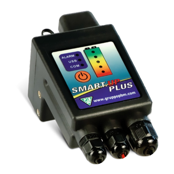
- Page 9 Possibility to download data on a USB stick Insert the USB stick with the SmartUP connected to the batteries. Keep the red button pressed for about 10 seconds until the USB LED starts to flash. Wait for the data download and then disconnect the USB stick. ...
Need help?
Do you have a question about the ABS-LINE SMART-UP and is the answer not in the manual?
Questions and answers