Table of Contents
Advertisement
Quick Links
Table of contents:
1
EVK FEATURES ........................................................................................................................................................ 2
2
KIT CONTENTS ......................................................................................................................................................... 2
3
SYSTEM REQUIREMENTS ....................................................................................................................................... 2
4
GETTING STARTED .................................................................................................................................................. 3
4.1
4.2
V
4.3
5
CONNECTING THE STIM TO YOUR PC .................................................................................................................. 6
6
USING PC SOFTWARE ............................................................................................................................................. 7
7
INTRODUCTION TO PC SOFTWARE .................................................................................................................... 12
7.1
7.1.1
Service mode panel ................................................................................................................................... 12
7.1.2
Measure panel ........................................................................................................................................... 13
7.1.3
Logging panel ............................................................................................................................................. 13
7.2
7.3
7.4
7.5
7.6
7.7
7.8
DOK452 rev.0
USER MANUAL
............................................................................................................................ 6
.............................................................................................................................................. 12
............................................................................................................................................... 14
................................................................................................................... 15
................................................................................................................... 15
........................................................................................................................... 15
.................................................................................................................................................. 17
............................................................................................................................................ 18
.......................................................................................................................... 19
STIM210 Evaluation Kit - USB
...................................................................................................... 4
............................................................................................ 4
1/20
EvaluationTools
2020
Advertisement
Table of Contents

Related Manuals for sensonor STIM210


Summary of Contents for sensonor STIM210
-
Page 1: Table Of Contents
USER MANUAL EvaluationTools STIM210 Evaluation Kit - USB Table of contents: EVK FEATURES ................................ 2 KIT CONTENTS ................................. 2 SYSTEM REQUIREMENTS ............................2 GETTING STARTED ..............................3 FTDI ...................... 4 NSTALLATION OF SERIAL DRIVER .................... 4 ERIFICATION AND CONFIGURATION OF SERIAL DRIVER .......................... -
Page 2: Evk Features
Tool for fixing connector of communication and power cable to the gyro module Hard copy of User manual Note that the evaluation kit does not include a STIM210 gyro module. This must be ordered separately. System requirements Windows XP SP2 (or later), Windows Vista, Windows 7 (32/ 64bit) , Windows 10 (32/ 64bit) ... -
Page 3: Getting Started
USER MANUAL EvaluationTools STIM210 Evaluation Kit - USB Getting started Preparing your system involves the following steps: FTDI Serial Driver installation Serial Driver verification EVK PC Software installation DOK452 rev.0 3/20 2020... -
Page 4: Usb Kit Installation Of Ftdi Serial Driver
Verify that the driver installation has completed successfully: Figure 1: COM port assignments for USB cable in Windows 7. Make a note of the assigned COM port value(s) information. This will be needed later for connecting to the STIM210 from the PC software. - Page 5 USER MANUAL EvaluationTools STIM210 Evaluation Kit - USB Select "Advanced" from the "Port Setting" tab. Set the "Receive (Bytes)" and Transmit (Bytes) settings to 256. Press OK twice. The computer may have to be restarted for the changes to take effect.
-
Page 6: Installation Of Pc Software
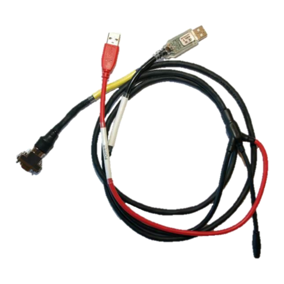
The PC software also can be downloaded from the Sensonor support site. Check this site regularly for updates. Connecting the STIM to your PC P-USB Micro-D USB- RS422 Figure 2 Connecting the STIM210 to the computer DOK452 rev.0 6/20 2020... -
Page 7: Using Pc Software
3. A pop-up box for software registration appears. Fill in the open fields and press "Submit". The default email client opens. Press "Send" in order to complete this step (user information is sent to Sensonor for support issues). This step will only have to be completed once. - Page 8 USER MANUAL EvaluationTools STIM210 Evaluation Kit - USB Figure 5: Welcome message and software registration 4. The Normal mode panel is shown Figure 6: Normal mode panel after selecting INI-file DOK452 rev.0 8/20 2020...
- Page 9 USER MANUAL EvaluationTools STIM210 Evaluation Kit - USB 5. Verify the correct COM port settings in the Parameters view. If needed port # setting needs to be changed, do this by double clicking on the value and enter correct value. The default password to edit is ‘stim’.
- Page 10 USER MANUAL EvaluationTools STIM210 Evaluation Kit - USB 7. Switch the ’ Initiate power-on sequence’ control switch position to ’On’ position. Do not insert the power supply cable at this point. The pop-up message asking for confirmation of bitrate appears. Press OK.
- Page 11 ‘Request serial# DG’ button. An example of such a result is shown in Figure 11. The system is now ready for use Figure 11: Result of sending ’Request serial# DG’ to the STIM210 DOK452 rev.0...
-
Page 12: Introduction To Pc Software
USER MANUAL EvaluationTools STIM210 Evaluation Kit - USB Introduction to PC software Panels overview In addition to the panel already shown (Normal mode and Parameters panel), other panels are also available: 7.1.1 Service mode panel Figure 12: Service mode panel DOK452 rev.0... -
Page 13: Measure Panel
USER MANUAL EvaluationTools STIM210 Evaluation Kit - USB 7.1.2 Measure panel Figure 13: Measure panel 7.1.3 Logging panel Figure 14: Logging panel (for saving data to file) DOK452 rev.0 13/20 2020... -
Page 14: Main Panel Menu
‘File’ → ‘Exit’ Exit program ‘Help’ → ‘Check for updates’ Opens the Sensonor support site in a web browser. New and updated Drivers, PC software and user manuals can be downloaded ‘Help’ → ‘About’ Information about the program (Program name, publisher and software revision... -
Page 15: Normal Mode Panel Descriptions
USER MANUAL EvaluationTools STIM210 Evaluation Kit - USB Normal mode panel descriptions Table 2: Normal mode panel descriptions. Panel unit Functionality and description Connect to HW Connects to interface hardware. Opens COM port according to settings specified in active parameter file Indicator for hardware connection. - Page 16 USER MANUAL EvaluationTools STIM210 Evaluation Kit - USB Save to file button Saves data from a completed measurement series to a result file. The file path defined in the active parameter file is proposed X-, Y- and Z-axis check boxes...
-
Page 17: Logging Panel
USER MANUAL EvaluationTools STIM210 Evaluation Kit - USB GYRO_TMP_STS Gyro temperature status Counter Sample counter. See product datasheet for details Latency Sample latency. See product datasheet for details RxCRC Received CRC CalCRC Calculated CRC DG_ID Datagram identifier Logging panel Table 6: Logging panel descriptions. -
Page 18: Parameters Panel
USER MANUAL EvaluationTools STIM210 Evaluation Kit - USB Parameters panel Table 7: Parameters panel descriptions. Panel unit Functionality and description ===== General parameters ===== Password Current valid password to be able to edit the parameters list. The password is “stim”... -
Page 19: Messages From The Program
USER MANUAL EvaluationTools STIM210 Evaluation Kit - USB Messages from the program Messages that the program can display are listed inTable 8: Table 8: Possible messages given by the program. Message Description The program is already started, a second instance will... - Page 20 You are about to change the RS422 bit rate. If are you using the USB kit hardware provided by Sensonor, please notice that you will not be able to A warning to the user about limitations for certain RS422 communicate with the device if you change to something...
Need help?
Do you have a question about the STIM210 and is the answer not in the manual?
Questions and answers