Table of Contents
Advertisement
FIESSLER
E L E K T R O N I K
EC type examination certified
Zertifiziertes QM-System
nach DIN ISO 9001:2000
Fiessler Elektronik GmbH & Co. KG
Kastellstr. 9
D-73734 Esslingen
Press Brake Protection System safety category 4
Operating Instructions
AKAS®-LC-II M
AKAS®-LC-II F
CONTENTS:
Safety Instructions
Application
Instruction for use
Mechanical data
Electrical connection
Putting into operation
Telefon: 0711 / 91 96 97-0
Telefax: 0711 / 91 96 97-50 eMail: info@fiessler.de
AKAS®LC-II M
AKAS®LC-II F
E L E K T R O N I K
Internet: http://www.fiessler.de
Advertisement
Table of Contents

Summary of Contents for Fiessler AKAS LC-II M
- Page 1 Instruction for use Mechanical data Zertifiziertes QM-System Electrical connection nach DIN ISO 9001:2000 Putting into operation Telefon: 0711 / 91 96 97-0 Internet: http://www.fiessler.de Fiessler Elektronik GmbH & Co. KG Telefax: 0711 / 91 96 97-50 eMail: info@fiessler.de Kastellstr. 9 D-73734 Esslingen...
-
Page 2: Table Of Contents
1. Overrun Traverse Measuring ……………………………………………………………………………………………… 2. Design of a Mechanical Suspension Device - void if Fiessler Suspension Devices are used ……………………… 3. Mounting of the suspension devices at the ram ………………………………………………………………………… 4. Mounting of the AKAS® components at the suspension devices……………………………………………………... -
Page 3: Akas®Lc-Ii F
Indicator lights on Frontpanel and switches for safe operation FIESSLER E L E K T R O N I K AKAS®LC-II F E L E K T R O N I K view after removing the connection lid view of the receiver elements... -
Page 4: Akas®Lc-Ii M
FIESSLER LEDs and operating elements E L E K T R O N I K AKAS®LC-II M E L E K T R O N I K view of the receiver elements view after removing the connection lid on the receiver... -
Page 5: General Safety Instructions
Safety Instructions FIESSLER E L E K T R O N I K Please observe always models This is the operating instruction for the AKAS® AKAS®-LC IIM, AKAS®-LC IIF Special instructions for each model are provided with its individual model marking. -
Page 6: Prerequisites For Using The Press Brake Protection Akas
If not, it can be realised by the AKAS®-...F and a cam controller or by the Fiessler AMS-system . Before the initial start-up, the overrun traverse must be checked either by using the test rod (see page 5) or by using an Overrun Traverse measu- ring device. -
Page 7: Description And Fields Of Application For The Equipment
Description and fields of application for the equipment FIESSLER E L E K T R O N I K General Instructions The laser - accident preventing light barrier AKAS® is an electro sensitive protective and controlling device (ESPE) which has the function to protect operators from accidents. -
Page 8: Function Description / Characteristics
Description and fields of application for the equipment FIESSLER E L E K T R O N I K Function Description / Characteristics systems without operating mode se- systems with operating mode selec- lection tion operation only with additional safety with integrated safety fuunctions PLC (e.g. -
Page 9: Function Description During Bending Of Flat Sheet Metal / Bending Of Wavy Sheet Metal
Description and fields of application for the equipment FIESSLER E L E K T R O N I K Function description during bending of flat sheet metal Principle of function 1. Release the closing movement by activating the foot pedal. -
Page 10: Function Description During Box Bending / Bending Of Small Items
Description and fields of application for the equipment FIESSLER E L E K T R O N I K Function description during bending of boxes Function principle 1. "Box Bending" is activated by the box bending button. The signal at the box bending input KAST must be high box bending (+24V) for at least 100 ms and after that low (0V) for at least 100 ms. -
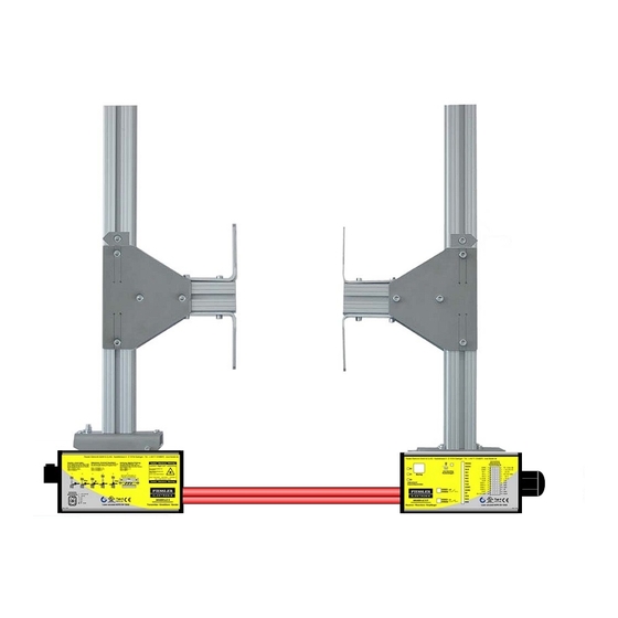
Page 11: Mechanical Data, Dimension Drawings
Mechanical data, dimension drawings FIESSLER E L E K T R O N I K AKAS®-LC II M / -LC II F transmitter and receiver max. Standard-Range max 4,5 m housing type The aluminium housing of both transmitter and receiver are powder coated in RAL 1020 yellow. The optical he- ad is made of acid-resistant spherically reinforced plastic (polyamide). -
Page 12: Mounting
Fiessler-mechanical holders Overrun traverse measurement How to proceed: Step by Design of the mechanical holders - void if Fiessler holders are used step mounting the AKAS® Mounting of the holders at the ram Mounting of the AKAS® at the ram Connection of the AKAS®... -
Page 13: Overrun Traverse Measuring
If not, it can be reali- Measurement sed by the AKAS®-...F and a cam controller or by the Fiessler AMS-system . Before the initial start-up, the overrun traverse must be checked either by using the test rod (see page 5) or by using an Overrun Traverse measuring device. -
Page 14: Design Of A Mechanical Suspension Device - Void If Fiessler Suspension Devices Are Used
Design of the holders / Mounting of the holders at the ram 2. design of the holders - The dimensions of the self-supplied holders must be individually laid out according to the dimen- void if Fiessler holding Devices sions of the press brake. are used - The self-supplied holders must be made of torsion-free rigid material, e.g. -
Page 15: Mounting Of The Akas® Components At The Suspension Devices
The adjustment screws must be easily longitudinal axis Fiessler Elektronik OHG - Kastellstrasse 9 - D 73734 Esslingen - Tel.: 0711/9196970 Hintere Anschlussreihe am Empfängersupport: accessible. Pay attention to avoid any 1h = + Motor... - Page 16 Mounting FIESSLER E L E K T R O N I K Adjustment of the AKAS® at the first installation To guarantee a trouble-free operation, the mecanical 6. Adjustment of the fixtions of both the receiver and the transmitter must be AKAS®...
- Page 17 Mounting FIESSLER E L E K T R O N I K adjustment of the AKAS® at the first installation fine adjustment The holder of the transmitter must be turned around both the longitudinal and vertical axis until the laser beams are aligned parallel to the ram.
- Page 18 The beam hits the target circle at the The transmitter must be turned to the left tool end, at the right tool end the right in the slot, i.e. on the Fiessler hol- beam edge is lower than the target cir- ders, the inclination adjustment screw cle = case B Fig.
- Page 19 Mounting FIESSLER E L E K T R O N I K adjustment of the AKAS® at the first installation adjustment control - LEDs Ausricht- synchronization transmitter - receiver AKAS®-LC II M / - F kontrollen transmitter-beam does focus at all...
- Page 20 Mounting FIESSLER E L E K T R O N I K adjustment directions - after tool change When using frequently upper tools with different hights, the system AKAS®-II or AKAS®-3 is recommended owing to the enhanced operating convenience during the tool change.
-
Page 21: Self-Acting Overrrun Traverse Test
Mounting FIESSLER E L E K T R O N I K 5.9, 5.10 Automatic overrun traverse test 8. Verification of all electrical see chapter 6 Electrical connections connections referring to safety class 4 9. Automatic overrun According to prEN 12622, the overrun traverse of the machine must be verified automatically at the first stroke traverse test after its connection to power of the press brake or of the AKAS®... -
Page 22: Electrical Connections -Descriptions / Wiring Diagrams
Any modification of the specified circuits can cause hazardous states and is therefore forbidden. If the press does not posssess any position-monitored contactors for the seitch-over from fast speed into slow speed, a safe integration is possible using the Fiessler AMS-System. Doku Nr. 995 Stand 1.12.2011 / Aui... -
Page 23: Instructions For Integrating The Akas® Inti The Machine Control System
Electrical connections - Description / Wiring diagrams FIESSLER E L E K T R O N I K Directions for the integration into the machine control system Muting signal Muting signal from the machine control system: (Mutingsignal available from the contactor position control of the working stroke valve, from the pressure switch... -
Page 24: Akas®-Lc Ii M
Electrical connections - Description / Wiring diagrams FIESSLER E L E K T R O N I K -operation only with additional safety PLC (e.g. FPSC) AKAS®-LC II M function - protection of the operator from being squeezed between the ram and the matrix (all other safety monitoring functions are carried out by a safety control (e.g. -
Page 25: Connection
Electrical connections - Description / Wiring diagrams FIESSLER E L E K T R O N I K AKAS®-LC II M AKAS®-LC II F --with HEX switch position 00 00 --operation only with additional safety PLC (e.g. FPSC) AKAS®-LC... AKAS®-LC... Sender... -
Page 26: Akas®-Lc Ii F
Electrical connections - Description / Wiring diagrams FIESSLER E L E K T R O N I K -with selectable safety functions AKAS®-LC II F functions AKAS®-LC II F provide - apart from the standard functions - more safety functions which enable the mo- ritoring and control of a press brake without additional safety PLC. - Page 27 Electrical connections - Description / Wiring diagrams FIESSLER E L E K T R O N I K -with selectable safety functions AKAS®-LC II F position of HEX-switches position of HEX-switches Terminals B8 B8 oder F8 F8 Terminals of the Receiver AKAS®-LCF 00 00 AKAS®-LCF...
-
Page 28: Connection Example: Safety Monitoring Of The Machine By Akas
Electrical connections - Description / Wiring diagrams FIESSLER E L E K T R O N I K -with selectable safety functions AKAS®-LC II F Machine-Safety monitoring by AKAS®-...F wiring diagram 2/S.28 Doku Nr. 995 Stand 1.12.2011 / Aui... -
Page 29: Akas
Electrical connections - Description / Wiring diagrams FIESSLER 6.5.1 E L E K T R O N I K -with selectable safety functions AKAS®-LC II F 1. operation with additional The safety PLC is responsible for the fast speed / slow speed position control and provides this state to Safety PLC the AKAS€... -
Page 30: Monitoring Of The Stop Valves (Edm)
Electrical connections - Description / Wiring diagrams FIESSLER 6.5.1 E L E K T R O N I K -with selectable safety functions AKAS®-LC II F 5. Control of the stop contac- AKAS® monitors in a safe way both positions of the stop- and the fast speed closing state of the contac-... -
Page 31: Connection: Safety Light Grid ( Equivalent Switching) As Rear Guard
Instead of using a rear protective metal grid, a safety light grid with equivalent switching outputs, e.g. with lightgrid type Fiessler ULVT / TLVT or ULCT / TLCT as shown in wiring diagram 6/S.31 is possible. with equivalent switching outputs... -
Page 32: Installation Operation / Protection By Monitored Slow Speed Wiithout Activated Protective Field
Electrical connections - Description / Wiring diagrams FIESSLER 6.5.1 E L E K T R O N I K -with integrated safety functions AKAS®-LC II F 7. Installation operating mo- A selector switch provides the possibility to choose between operating mode with activated protective de, i.e. -
Page 33: Information About The Traverse In Slow Speed -Connection Of Traverse Measuriung Device
During the operation with slow speed traverse information, the upper receiver elements are only muted if information a +24 V signal is given to KAST. This signal is provided by a traverse measuring system (e.g. Fiessler AMS, or NC) which indicates that the traverse has been actually covered. By this, the upper receiver elements remain activated as longh as possible even in the case of a very low slow speed, and interme- diate stops during slow speed. -
Page 34: Programming Of The Safety Functions By Hex Switches
Electrical connections - Description / Wiring diagrams FIESSLER 6.5.2 E L E K T R O N I K Programming of the integrated safety functions via Hex-switches By the use of 4 Hex switches different operating modes can be selected. - Page 35 Electrical connections - Description / Wiring diagrams FIESSLER 6.5.2 E L E K T R O N I K Programming of the integrated safety functions via Hex-switches The Hex-switches must always be programmed in pairs (1 and 3, 2 and 4). Within each pair, equal values must be programmed.
-
Page 36: Displaying Outputs, Indicator-Leds
Electrical connections - Description / Wiring diagrams FIESSLER E L E K T R O N I K Displaying outputs Displaying of conditions lamp is out (flashing is hardly recognizable) : during the closing movement the proitective field is at least parti-... -
Page 37: Outputs Via Serial Rs232-Interface
Electrical connections - Description / Wiring diagrams FIESSLER E L E K T R O N I K Displaying outputs Status messages, The AKAS® displays messages by serial transfer via its RS 232 interface; transfer format: 9600 baud, 1 start warnings and Error bit, 8 data bits, 1 stop bit. - Page 38 I nternal error if this is displayed again after the voltage reset, a ve- protective circuit rification by Fiessler Elektronik is necessary other message or error within the protective open again all protective grids and Emergency off...
- Page 39 Fiessler Elektronik is ne- cessary 90 / 102 89 / 101 Problem fast speed -- line short circuiting of the SG A circuit with an-...
-
Page 40: Service / Maintenance / Warranty
Returning a unit If, in the case of default, the necessity of returning the unit to Fiessler Elektronik arises, it will be very advantageous for a fast default diagnosis if the following topics are observed and observed:... -
Page 41: Order Codes
Order codes assesories FIESSLER E L E K T R O N I K AKAS® accessories part designation order code (electronic equipment) AKAS® Muting System w. integrated overrun traverse control AMS/N/K AMS/N, complete (incl. 2 magnetic sensors with 10m & 5m... -
Page 42: Akas®-Inspection Sheet
AKAS®-Inspection Sheet Inspection Sheet Inspection of a press brake safeguarded by a press No.: brake protection system AKAS® Date: Hex switch positions:____________________________ customer‘s order number: machine builder company: Serial no.. machine type: address: machine control by: department: machine located at: Post Code/City: inventory no.: cost centre:... -
Page 43: Declaration Of Conformity
Declaration of conformity FIESSLER E L E K T R O N I K FIESSLER E L E K T R O N I K Fiessler Elektronik GmbH & Co. KG Kastellstr. 9 D -73734 Essling e n GESCHÄFTSLEITUNG Modèle recommandé... -
Page 44: Terms
Standard Installation range Maximum distance between transmitter and receiver is 6 m ( For longer range please get in contact with Fiessler Elektronik or your local dealer). Overrun The part of the hazardous motion still taking place after interrupting the light beam. - Page 45 Notes FIESSLER E L E K T R O N I K Doku Nr. 986 Stand 1.12.2011 / Aui...
- Page 46 Safety-Light-Grid with muting function Service As a special feature for training our customers, Fiessler Elektronik offers one-day safety workshops. Our service team provides you with expert advice and information for the reliable integration of our safety equipment into your machine.
Need help?
Do you have a question about the AKAS LC-II M and is the answer not in the manual?
Questions and answers