Advertisement
STEP 1
- Determine Mounting Location
•
Proximity -
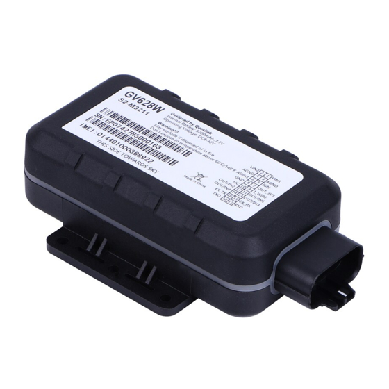
The GV628W Tracker Unit should be mounted near an external power source, or in the case of
temperature tracking, within the reefer fairing.
•
View of the sky
- Since the GPS satellites beam location information to the device, it needs to have a view of the
sky. The GPS signal can penetrate glass, plastic, and wood, but not metal. Here are some suggested locations:
> BEST - Behind a plastic barrier and or glass, shielded from the weather and hidden from view.
> GOOD - Mounted in an open area with direct access to the sky.
> FAIR - Hidden with an indirect view of the sky.
•
OPTIONAL Temperature Probe(s) -
refrigeration system. The silver tip of the temperature probe is the sensor. It should be exposed directly to the air
being monitored. Do not cover the sensor, or mount the sensor directly to an exterior wall. Excess wire should be
coiled (DO NOT cut). Cables should be secured along the run with clamps or cable ties.
STEP 2
- Terminate Electrical Connections
We recommend soldering all electrical connections. If that is not possible, appropriate
sized wire tap connectors (posi-tap.com) like the ones pictured here should be used.
Do not jam wires between fuse and fuse holder.
•
Primary Device Wires
-
R E
D,
R E D
/G R E E N
>
R E D
is Main power which goes to a constant power connection with a voltage between +12V
and +24V. (Blue wire on trailers, constant battery circuits on other applications)
>
R E D
/G R E E N
+12V and +24V. (Trailer Clearance or Parking Lights wire on Trailers, a different constant battery circuit in
other applications). If no alternate power is available, connect to the same source as RED Main wire.
BLACK
> Two
[Battery(-)] using a ring connector or are tapped
into an existing ground wire.
>
W H I T E
is for system run detection. For Reefers,
connect to a circuit that is active only when the
refrigeration system is in the RUN position. For
Other Vehicles connect to a circuit that is on
when the engine is running (Key ON). For non-
powered Trailers, connect to a circuit that receives
power when the tow vehicle is connected. This
circuit should be between +12V and +24V when
active, and +0V (or Open) when inactive (see
the diagram on the next page).
• Optional Device Wires - Temperature Probe
Equipped Units, connect the GRAY Tracker wire
to the YELLOW wire(s) on the Temperature
Probe(s) and connect the BLACK/WHITE STRIPE
Tracker Wire to both the Red and Green wires
of the temperature probe(s). The other Tracker
wires are for optional I/O sensors that incur
additional monthly charges. Tape or heat-shrink
insulate the ends if not in use.
Proper connection of the RED, BLACK, and WHITE wires is essential for the device to operate
Tracker Systems, Inc.
GV628W
GV628W
G P S Tr a c k e r
Installation
A single probe will usually be located near the return air duct of the
- There are five wires that need to be connected to an external power source
BLACK
, 2
,
W HITE
.
is backup power which goes to a constant power connection with a voltage between
wires go to chassis ground
www.trackersystems.net
Guide
Color
Description
Comment
Red
PWR 1
Primary power input, 8-32V DC
Red/Grn
PWR 2
Secondary power input, 8-32V DC
Black
GND 1
Primary Ground (to vehicle's frame) 3
Black
GND 2
Secondary Ground
White
Ignition
Ignition input, positive trigger
Green
ADIN 1
Analog Input 0-32V
Red/White
3V Output
External Acc'y PWR (250mA Max)
Black/White
Ground
External Acc'y Ground
Gray
1-Wire
Temperature Sensor Input
NC
NC
Blue
I/O 1
Negative trigger input for normal
Yellow
I/O 2
use or open drain output 150mA
Brown
I/O 3
Orange
I/O 4
Purple
EX RX
UART RXD TTL
Purple/White
EX TX
UART TXD TTL
Pink
RXD
UART RXD TTL
White/Black
TXD
UART TXD TTL
Description of GV628W Power Cable
Pin #
1
2
4
5
6
7
8
9
10
11
12
13
maximum drive current
14
15
16
17
18
877-872-2521
Advertisement
Table of Contents

Summary of Contents for Tracker Systems GV628W
- Page 1 STEP 1 - Determine Mounting Location • Proximity - The GV628W Tracker Unit should be mounted near an external power source, or in the case of temperature tracking, within the reefer fairing. • View of the sky - Since the GPS satellites beam location information to the device, it needs to have a view of the sky.
- Page 2 - Test and Secure Device As soon as the GV628W has been connected to power, the LED lights located in the white strip on the side of the device will begin to blink. The Power LED will appear first, followed by the GSM LED, and last, the GPS LED. If the device is being powered up for the first time, the GPS LED may take a number of minutes to appear.
Need help?
Do you have a question about the GV628W and is the answer not in the manual?
Questions and answers