Advertisement
Table of Contents
- 1 Table of Contents
- 2 Introduction
- 3 Safety Standards
- 4 Technical Data
- 5 Installation
- 6 Foundation and Anchoring Machine
- 7 Electric Wiring
- 8 Air Connection
- 9 Ethernet Connection
- 10 Machine Locking Mechanisms
- 11 Shipping Information
- 12 Cleaning Machine after Installation
- 13 Maintenance
- Download this manual
Advertisement
Table of Contents

Summary of Contents for FLEX CNC C Series
- Page 1 C-Series Installation & Maintenance Manual Page 1 of 18...
-
Page 2: Table Of Contents
Table of Contents: 1. Introduction: Page 3 2. Safety Standards: Page 4 3. Technical Data: Page 5 4. Installation: Page 8 5. Foundation and anchoring machine: Page 10 6. Electric wiring: Page 11 7. Air Connection: Page 13 8. Ethernet connection: Page 14 9. -
Page 3: Introduction
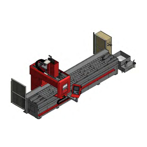
Introduction: The purpose of this manual is to describe the procedures for the installation and maintenance of the FlexCNC C-Series milling machine. The operator or person responsible for the operation of this machine should carefully read this manual in order to be familiar with the different parts of the machine. At the time this manual was prepared, assembly drawing, part numbers and the descriptions of the various operations, coincided with the characteristics and operation mode of the machine. -
Page 4: Safety Standards
Safety Standards: Improper use of equipment can produce serious injuries for the operator or any person in the immediate area. We strongly suggest that these safety standards are read carefully by the operator or maintenance personnel before using machine to prevent serious injury. -
Page 5: Technical Data
Technical Data: Construction: Welded frame made with structural tubes allow for greater absorption of vibrations and are more rigid and stable. Gantry is made from welded steel plate with reinforcing ribs to increase rigidity. Linear guides: The linear are made from tempered steel, polished and ground to allow for a low friction coefficient. - Page 6 Page 6 of 18...
- Page 7 Coolant System: The coolant tank is located to right end of the machine looking from the front of the machine. There is one motor and pump which is fixed to the coolant tank which provides coolant to the machine. The capacity is: 175 Liters/46.25 gallons 350 Liters/92.5 gallons Chip Conveyor:...
-
Page 8: Installation
Installation Machine Location: DO NOT place the machine in the following conditions: • Places where the machine would be exposed directly to solar rays or a heat source • Places where there are usual changes of air, relative humidity, and/or relative humidity is too high (75%) •... - Page 9 DANGER!!!! Don´t pass underneath hoisted loads! Page 9 of 18...
-
Page 10: Foundation And Anchoring Machine
Foundation and Anchoring: • Steel plate dimensions 2 in. X 6 in. X .75 in. • Move the machine to appropriate location and lower the machine to the floor. • Mark the location where lag will need to be placed. •... -
Page 11: Electric Wiring
Electric Wiring: DANGER!! Make sure the main power supply to the machine is off to prevent accidental shock. After the machine is installed, connect the machine to a suitable power supply line. To do this, prepare a cable for 4 wires (3 phases + ground) suitable for the required power. This will supply the autotransformer. - Page 12 Page 12 of 18...
-
Page 13: Air Connection
Air Connection: This connection is on the right back side of the machine looking from the control side and near the chip conveyor exit. There is a filter with a filtering capacity of 5 seconds with automatic purge. Provide enough flow of dry and clean air to the machine with a pressure between 90 and 101 psi of dry and clean air. -
Page 14: Ethernet Connection
Ethernet Connection: Ethernet connection; Connect a CAT-6 Ethernet Cable to any network access point to fitting on the right side of the machine. We will be need it for service for remote troubleshooting. Maximum cable length should be less than 330 feet. For longer connections use any bridge device. -
Page 15: Machine Locking Mechanisms
Machine Locking Mechanisms: The following needs to be added to the machine for moving, transportation, and lifting. Below is the support for the Z axis. It is attached to the head to keep Z axis in its lowest position. It also prohibits X, Y, and Z axis from moving. Below is also an extra support for the X axis, the bracket is located on the rear of the machine. -
Page 16: Shipping Information
Shipping Information: Cleaning Machine After Installation: To prevent rust during shipping, all exposed machined surfaces are coated with antirust oil. This coating and any dust or foreign particles accumulated during shipment could prematurely deteriorate sliding surfaces in the machine unless they are removed before putting the machine into operation. -
Page 17: Maintenance
Maintenance: Safety Precautions: Following the recommendations listed below may minimize accidents caused when performing maintenance operations. However, depending on machine location and type of work (plus other factors) the following additional precautions could be appropriate. • Maintenance operations shall only be performed by qualified individuals. Maintenance personnel shall only perform maintenance operations for which they are specifically trained. - Page 18 • Remove chips, dust and foreign particles from machine table and bed. • Wipe off oils, fluids and chips from machine table. • Clean all sliding surfaces. • Clean bearing wipers. • Clean exposed surfaces on tools in tool carousel. •...
Need help?
Do you have a question about the C Series and is the answer not in the manual?
Questions and answers