
Summary of Contents for Messtechnik Sachs Irinos IR
- Page 1 ® Irinos IR Users Manual © 2015 - 2016 Messtechnik Sachs GmbH, Germany This users manual has been optimized for an interactive web view. Use the PDF version only, if no access to the web version is available.
-
Page 3: Table Of Contents
IR-DIO with digital in- and outputs ................54 IR-PU power supply (industrial version) ..............57 I/O-Boxes for the IO-Bus (desktop version) ............... 59 I/O-Boxes for the IO-Bus (hat / din rail version) ............60 Irinos IR Users Manual © 2015 - 2016 Messtechnik Sachs GmbH, Germany... -
Page 4: Table Of Contents
Connecting analogue sensors ................108 6.4.7 Connecting digital in- and outputs ............... 108 Setup First steps ........................110 Box addressing ......................110 Network configuration ....................112 Irinos-Tool ........................113 Web-Server ......................... 114 Irinos IR Users Manual © 2015 - 2016 Messtechnik Sachs GmbH, Germany... -
Page 5: Table Of Contents
10. Maintenance, cleaning and disposal 10.1 Maintenance ......................188 10.2 Cleaning ........................188 10.3 Disposal ........................189 11. Application notes 11.1 Incremental encoders 1Vpp or TTL/RS422 ............... 192 Irinos IR Users Manual © 2015 - 2016 Messtechnik Sachs GmbH, Germany... -
Page 6: Table Of Contents
12. Specifications & dimensions 12.1 Common specifications ....................200 12.2 Dimensions Irinos-Box ....................202 12.3 Dimensions power supply IR-PU50 ................205 12.4 Dimensions front-side mounting adapter IR-MFFM-1 ..........208 Index Irinos IR Users Manual © 2015 - 2016 Messtechnik Sachs GmbH, Germany... -
Page 7: Introduction
Introduction... -
Page 8: Imprint
All product names used in this manual are trademarks of their respective owners. Material-No. 785-1018 Change not Subject to change without notice. Release date 20/06/2016 Revision history Changes First revision Irinos IR Users Manual © 2015 - 2016 Messtechnik Sachs GmbH, Germany... -
Page 9: Legal Notes
With the exception of the Messtechnik Sachs logo, the user has the right to use pictures and texts from the operating instructions/documentation for creating the user's own machine and system documentation. - Page 10 2. The information contained in an item of electronic documentation can be amended by Messtechnik Sachs without prior notice and does not commit Messtechnik Sachs in any way. 3. Messtechnik Sachs guarantees that the software program it created agrees with the change description and program...
-
Page 11: Warning Notice System
In such a case, the liability of Messtechnik Sachs is limited to the damage recognisable by Messtechnik Sachs when the specific circumstances are made known. -
Page 12: Qualified Personnel
We can, however, not exclude discrepancies and do therefore not accept any liability for the exact compliance. This documentation is reviewed regularly. Corrections may be contained in newer versions. Irinos IR Users Manual © 2015 - 2016 Messtechnik Sachs GmbH, Germany... -
Page 13: Preface
Other fields of application, which are not mentioned but similar, are also excluded from use. In safety critical areas, the safety in operation must be ensured by external equipment (e.g. external emergency stop). Please note: Irinos IR Users Manual © 2015 - 2016 Messtechnik Sachs GmbH, Germany... -
Page 14: Required Knowledge
Introduction Warning Products from Messtechnik Sachs GmbH must only be used for applications, which are mentioned in the dataheet or in the related documentation. If third party products are used, these must be recommended or permitted by Messtechnik Sachs GmbH. Proper and safe operation of the products require appropriate transportation, storage, mounting, usage and maintenance. -
Page 15: Safety Instructions
Safety instructions... - Page 16 Do not place sources of radiation next to the Irinos measurement system. o Turn off devices, which are a source of radiation. o Reduce the radio performance of radiation emitting devices. Ensure the compliance regarding electromagnetic compatibility. Irinos IR Users Manual © 2015 - 2016 Messtechnik Sachs GmbH, Germany...
- Page 17 Observe the additional requirements for PELV supply circuits according to IEC60204-1. Only use power supplies, which allow a safe separation of the operating voltage and the load voltage according to IEC60204-1. Irinos IR Users Manual © 2015 - 2016 Messtechnik Sachs GmbH, Germany...
- Page 18 Do not open the Irinos-Box. Thereby you avoid touching the sensitive devices. Irinos IR Users Manual © 2015 - 2016 Messtechnik Sachs GmbH, Germany...
- Page 19 Avoid direct heat radiation next to the Irinos-System. o If moisture is present, wait until the Irinos-System has completely dried (ca. 8 hours). Irinos IR Users Manual © 2015 - 2016 Messtechnik Sachs GmbH, Germany...
- Page 20 Inappropriate cleaning agents may damage the device. Only use washing-up liquid for cleaning. Do not use: o Aggressive solvents and abrasive cleaner o Steam jet o Compressed air o Vacuum cleaner Irinos IR Users Manual © 2015 - 2016 Messtechnik Sachs GmbH, Germany...
- Page 21 If the Irinos-System is in operation while cleaning, this may result in unintended actions. This may lead to personal injury or damage at machinery. Always turn off the Irinos-System before cleaning. Irinos IR Users Manual © 2015 - 2016 Messtechnik Sachs GmbH, Germany...
-
Page 23: System Overview
System overview... -
Page 24: System Concept
An important characteristic of the system is its independency of the time-behaviour of the PC. Concentricity and form measurement are possible with almost all standard PCs, even Laptops. No special hardware or realtime functionality is required. Reading measurement Irinos IR Users Manual © 2015 - 2016 Messtechnik Sachs GmbH, Germany... -
Page 25: Modularity
API. This DLL runs with all current Windows versions (Windows XP, Vista, 7, 8, 10). Measurement-PC and measurement-software are available from Messtechnik Sachs. Together with the Irinos-System, they build a complete measurement system. Because of the open concept, the Irinos-System can also be combined with measurement PCs of various other vendors. -
Page 26: Synchronisation
PC. Depending on the variant, it has digital in- and outputs and analogue inputs. Typically it is used together with at least one Slave-Box. The integrated Master is a measurement Box with integrated Irinos IR Users Manual © 2015 - 2016 Messtechnik Sachs GmbH, Germany... -
Page 27: Digital In-/Outputs (Bit-I/O)
PLC and the measurement software (e.g. start measurement, stop measurement, result ok, ...). Alternatively a ProfiNet module is available. Irinos IR Users Manual © 2015 - 2016 Messtechnik Sachs GmbH, Germany... -
Page 28: Power Supply
...): an external 24 V power supply is required for the in- and outputs. - I/O-Boxes connected via the IO-Bus. Depending in their type, some have an integrated power supply, some require a separate Irinos IR Users Manual © 2015 - 2016 Messtechnik Sachs GmbH, Germany... -
Page 29: Mounting Options
Irinos-Box. o Via the frontside mounting kit IR-MFFM-1, each Irinos-Box can be accessed from the front side, e.g. for placement into a control cabinet. Irinos IR Users Manual © 2015 - 2016 Messtechnik Sachs GmbH, Germany... -
Page 30: Overview Of Components
PC 828- IR-MASTER- Master o IO-Bus via M8 5000 KB1-68-68-3- SYSP-ETHIL o 4 digital inputs via 2x M12 o 4 digital outputs via 2x Irinos IR Users Manual © 2015 - 2016 Messtechnik Sachs GmbH, Germany... - Page 31 M12, e.g. for push buttons 828- IR-TFV-8-IET- Slave 8 inputs for probes Knäbel 5007 M16-IL 828- IR-TFV-8-IET- Slave 8 inputs for probes Knäbel 5008 KF27-IL IET, indirectly connected Irinos IR Users Manual © 2015 - 2016 Messtechnik Sachs GmbH, Germany...
- Page 32 RS422 via DSUB 15-pin: pre-configured for 1Vss 828- IR-INC-4- Integrat o 4 inputs for incremental 5015 SELTTL- encoders 1Vss or TTL/ DSUB15F-ETHIL Master RS422 via DSUB 15-pin: pre-configured for TTL/ Irinos IR Users Manual © 2015 - 2016 Messtechnik Sachs GmbH, Germany...
- Page 33 (for low output power) 828- IR-DIO-16-16- Slave 16 digital inputs and 16 5020 D37-EXTP-IL digital outputs via DSUB 37-pin Terminal block connection via 828-5021 828- Terminal block Terminal block module for Irinos IR Users Manual © 2015 - 2016 Messtechnik Sachs GmbH, Germany...
- Page 34 IR-MITEM-40 Mounting kit for 40mm aluminium profile 5043 Item or similar 828- IR-MWIP-40 Stand for 40mm aluminium profile Item or 5044 similar (Does not contain Item profile and mounting kit IR- MITEM-40). Labelling Irinos IR Users Manual © 2015 - 2016 Messtechnik Sachs GmbH, Germany...
- Page 35 IR-ILINK-050-IP40 ILink cable 5059 828- IR-ILINK-100-IP40 ILink cable 5060 ILink-Kabel IP65 for the connection between two Irinos- Boxes 828- IR-ILINK-002-IP65 ILink cable 5061 828- IR-ILINK-010-IP65 ILink cable 5062 Irinos IR Users Manual © 2015 - 2016 Messtechnik Sachs GmbH, Germany...
- Page 36 828- IR-CETH-RJ45-M12-050 Ethernet cable 5052 828- IR-CETH-RJ45-M12-100 Ethernet cable 5053 828- IR-CETH-RJ45-M12-150 Ethernet cable 5054 Connection cable for quick-change system for IR-TFV 828- K8F27-D25-030 5067 828- K8F27-D25-050 5068 Irinos IR Users Manual © 2015 - 2016 Messtechnik Sachs GmbH, Germany...
- Page 37 Tesa halfbridge and compatible 820- Connection box AB4F27 Tesa for indirect connection of 4 2210 inductive probes Tesa halfbridge and compatible Connection boxes for Knäbel IET (to be used with IR-TFV-8- Irinos IR Users Manual © 2015 - 2016 Messtechnik Sachs GmbH, Germany...
- Page 38 I/O-Module with 8 digital in- and outputs for hat rail / din 1812 rail mounting 828- I/O-Module with 16 digital in- and outputs for hat rail / 1814 din rail mounting Irinos IR Users Manual © 2015 - 2016 Messtechnik Sachs GmbH, Germany...
-
Page 39: Product Descriptions
Product descriptions... -
Page 40: Common
Slave-Boxes, an Ethernet interface for the connection to the PC and two digital inputs , e.g. for the connection of a foot pedal or push button: Irinos IR Users Manual © 2015 - 2016 Messtechnik Sachs GmbH, Germany... -
Page 41: Status Via Led (Integrated Master)
Connections and signalling elements of a "Slave-Box" 4.1.1 Status via LED (integrated Master) Using an "integrated Master ", the status of the Irinos-Box is displayed via a status LED: Irinos IR Users Manual © 2015 - 2016 Messtechnik Sachs GmbH, Germany... -
Page 42: Status Via 7-Digit Display (Master & Slave)
7-digit display. If a Master IR-MASTER is used, it will be displayed on this box. If an integrated Master is used, it will be displayed on the first Slave-Box. Irinos IR Users Manual © 2015 - 2016 Messtechnik Sachs GmbH, Germany... -
Page 43: Ir-Master For The Communication With The Pc
Type IR-MASTER-KB1-68-68-3-SYSP-ETHIL is additionally equipped with 4 digital inputs, 4 digital outputs and 3 analogue inputs ±10V (see figure). The definition of the type string is as follows: Irinos IR Users Manual © 2015 - 2016 Messtechnik Sachs GmbH, Germany... - Page 44 2x2 digital inputs 2x2 digital outputs 3 analogue inputs ±10V IO-Bus - for the connection of I/O-Boxes Ethernet LEDs LED „Speed“ Status Connection speed 10 MBit/s Connection speed 100 MBit/s Irinos IR Users Manual © 2015 - 2016 Messtechnik Sachs GmbH, Germany...
- Page 45 Due to their high input impedance, the measurement value may float if no input signal is connected. This is not a defect. It is a consequence of the high-class input specificatons. Irinos IR Users Manual © 2015 - 2016 Messtechnik Sachs GmbH, Germany...
-
Page 46: Ir-Tfv For Inductive Probes
This is rarely the case. o Using the type KF27, the measurement probes are connected via a separate connection box. The definition of the type string is as follows: Irinos IR Users Manual © 2015 - 2016 Messtechnik Sachs GmbH, Germany... - Page 47 Product descriptions Connectors for "IR-TFV-8-x-M16-x" und "IR-TFV-8-x-M16IP-x" Connectors for "IR-TFV-8-x-KF27-x" Irinos IR Users Manual © 2015 - 2016 Messtechnik Sachs GmbH, Germany...
- Page 48 This event is signalled as followes: o The Status-LED flashes very fast (integrated Master). o The text "OSC" is displayed on the 7-digit display (Slave-Box). Irinos IR Users Manual © 2015 - 2016 Messtechnik Sachs GmbH, Germany...
- Page 49 In order to allow a quick exchange of the Irinos-Box by an identical type, all input channels are digitally pre-calibrated. The following table shows the value range: Irinos IR Users Manual © 2015 - 2016 Messtechnik Sachs GmbH, Germany...
-
Page 50: Ir-Ain With Analogue Inputs ±10V
The Irinos-Box IR-AIN is appropriate for the connection of 8 analogue signals ±10V. It is available with standard connectors or with IP65 connectors. The definition of the type string is as follows: Irinos IR Users Manual © 2015 - 2016 Messtechnik Sachs GmbH, Germany... - Page 51 Due to their high input impedance, the measurement value may float if no input signal is connected. This is not a defect. It is a consequence of the high-class input specificatons. Irinos IR Users Manual © 2015 - 2016 Messtechnik Sachs GmbH, Germany...
-
Page 52: Ir-Inc For Incremental Encoders 1Vpp Or Ttl / Rs422
Depending on the order number, all channels are either set to 1Vpp or TTL/RS422 as factory defaults. The definition of the type string is as follows: Connectors for "IR-INC" Connectors / elements connectors for incremental encoders Irinos IR Users Manual © 2015 - 2016 Messtechnik Sachs GmbH, Germany... - Page 53 After removing this error, the Irinos system must be restarted. A power supply error is signalled as follows: Irinos IR Users Manual © 2015 - 2016 Messtechnik Sachs GmbH, Germany...
-
Page 54: Ir-Dio With Digital In- And Outputs
With 4 connectors M23 for the connection of external connection modules. The supply for the in- and outputs is taken from the ILink supply power (for low power applications). Irinos IR Users Manual © 2015 - 2016 Messtechnik Sachs GmbH, Germany... - Page 55 With one connector DSUB 37-pin for direct connection. Via an adapter module (828-5021), the in- and outputs can be accessed via terminal blocks. The definition of the type string is as follows: Connectors for "IR-DIO-16-16-M23-EXTP-IL" Irinos IR Users Manual © 2015 - 2016 Messtechnik Sachs GmbH, Germany...
- Page 56 Product descriptions Connectors for "IR-DIO-16-16-D37M-EXTP-IL" Connectors for "IR-DIO-16-16-D37M-EXTP-IL" with terminal block adapter Connectors / elements o 16 digital in- and outputs via DSUB37 Irinos IR Users Manual © 2015 - 2016 Messtechnik Sachs GmbH, Germany...
-
Page 57: Ir-Pu Power Supply (Industrial Version)
The mains plug is equipped with a protective earth conductor. Hence no separate earth connection is required. However, it is important that the earth pin of the mains cable is connected to earth. The 24V Irinos IR Users Manual © 2015 - 2016 Messtechnik Sachs GmbH, Germany... - Page 58 Therefore it is advised to keep some margin. A short flickering of the load LED while the Irinos-System is in operation may indicate, that the power supply was overloaded for a Irinos IR Users Manual © 2015 - 2016 Messtechnik Sachs GmbH, Germany...
-
Page 59: I/O-Boxes For The Io-Bus (Desktop Version)
50 watts power supply. It supplies the internal electronics as well as the digital in- and outputs. Connectors for desktop I/O-Boxes Connectors o 8 or 16 digital in- and outputs via connectors o Connectors for IO-Bus Irinos IR Users Manual © 2015 - 2016 Messtechnik Sachs GmbH, Germany... -
Page 60: I/O-Boxes For The Io-Bus (Hat / Din Rail Version)
The I/O-Boxes provide additional in- and outputs for the Irinos-Box IR-MASTER . They are connected via the IO-Bus Types with 8 or 16 digital in- and outputs are available, both appropriate for hat / din rain mounting. Irinos IR Users Manual © 2015 - 2016 Messtechnik Sachs GmbH, Germany... - Page 61 Product descriptions Connectors for I/O-Box hat/din rail with 16 I/Os Connectors for I/O-Box hat/din rail with 8 I/Os The power supply must be connected to terminal block PL5: Irinos IR Users Manual © 2015 - 2016 Messtechnik Sachs GmbH, Germany...
- Page 62 DIP-switch: Switch Function Termination enabled Termination disabled IO-Bus - Address 2 IO-Bus - Address 4 IO-Bus - Address 6 IO-Bus - Address 8 Irinos IR Users Manual © 2015 - 2016 Messtechnik Sachs GmbH, Germany...
- Page 63 Product descriptions The DIP-switch SW2 must always have the following switch settings: Switch Note Use these switch settings Irinos IR Users Manual © 2015 - 2016 Messtechnik Sachs GmbH, Germany...
-
Page 65: Pin Assignment
Pin assignment... -
Page 66: Ilink Connector (Master, Integrated Master & Slave)
Power supply via ILink interface Pin Description Note IL_Data1 Data 1 Ground potential for data lines IL_GND (not connected to the power supply or the internal supply of the Irinos-Box) Irinos IR Users Manual © 2015 - 2016 Messtechnik Sachs GmbH, Germany... - Page 67 I_GND the Irinos-System. Must be connected to Pin 15. IL_Data6 Data 6 Ground potential for the power supply of I_GND the Irinos-System. Must be connected to Pin 13. Irinos IR Users Manual © 2015 - 2016 Messtechnik Sachs GmbH, Germany...
-
Page 68: Ethernet (Master & Integrated Master)
It has an integrated "crossover-detection". Therefore it does not matter, whether a standard cable or a crossed cable is used. Pinning of the ethernet interface Irinos IR Users Manual © 2015 - 2016 Messtechnik Sachs GmbH, Germany... -
Page 69: Digital Inputs (Integrated Master)
Irinos system. It is appropriate for the supply of buttons or switches, which are connected to the digital inputs (e.g. foot pedals or push buttons). Irinos IR Users Manual © 2015 - 2016 Messtechnik Sachs GmbH, Germany... -
Page 70: Digital Inputs M12 (Ir-Master)
è This description is valid only for the digital inputs of the Irinos- IR-MASTER . The digital inputs of the integrated Master are almost identical: they provide a lower 24V output power. Irinos IR Users Manual © 2015 - 2016 Messtechnik Sachs GmbH, Germany... -
Page 71: Digital Outputs M12 (Ir-Master)
Connector for digital inputs M12 Description Note 24V Out 24V Output Digital input 2 Ground for digital inputs Digital input 1 Digital outputs M12 (IR-MASTER) è Connector type: M12 5-pin female, A-coded Irinos IR Users Manual © 2015 - 2016 Messtechnik Sachs GmbH, Germany... -
Page 72: Digital In-/Outputs M23 (Ir-Dio-16-16-M23-Xx-Il) And I/O-Boxes For Io-Bus
24V Output OUT2 Digital output 2 Ground for digital outputs OUT1 Digital output 1 Digital in-/outputs M23 (IR-DIO-16-16-M23-xx-IL) and I/O-Boxes for IO-Bus è Connector type: M23 16-pin female Irinos IR Users Manual © 2015 - 2016 Messtechnik Sachs GmbH, Germany... - Page 73 "quick connect elements" with M12 or M8 connectors. These are available from different suppliers (e.g. MurrElektronik, Turck, Weidmüller, PhönixContact, Erni, Escha). Connectors for digital in-/outputs M23 Irinos IR Users Manual © 2015 - 2016 Messtechnik Sachs GmbH, Germany...
-
Page 74: Power Supply For Digital In- And Outputs M12 (Ir-Dio-16-16-M23-Extp-Il)
Power for the digital in- and outputs must be supplied via this connector. Make sure to use a power supply, which fulfills the requirements of the protecion class PELV! Irinos IR Users Manual © 2015 - 2016 Messtechnik Sachs GmbH, Germany... -
Page 75: Digital In-/Outputs Dsub 37 (Ir-Dio-16-16-D37-Extp-Il)
Connector for I/O power supply via M12 Pin Description Note Ground 24V In 24V Supply input Protective earth Digital in-/outputs DSUB 37 (IR-DIO-16-16-D37-EXTP-IL) è Connector type DSUB 37-pin, male Irinos IR Users Manual © 2015 - 2016 Messtechnik Sachs GmbH, Germany... - Page 76 In order to fulfill the requirements of the protection class IP65, an IP65 DSUB connector housing from FCT / Molex is required. Connector DSUB37 for digital in- and outputs Irinos IR Users Manual © 2015 - 2016 Messtechnik Sachs GmbH, Germany...
- Page 77 IN15 Input 15 34 OUT15 Output 15 IN16 Input 16 35 OUT16 Output 16 Ground for Ground for 36 GND digital in- & digital in- & outputs outputs Irinos IR Users Manual © 2015 - 2016 Messtechnik Sachs GmbH, Germany...
-
Page 78: Analogue Inputs ±10V (Ir-Master & Ir-Ain)
(input) supply (input) 24V_In Analogue inputs ±10V (IR-MASTER & IR-AIN) è Connector type M16 7-pin, female Each connector provides one analogue input ±10V: Connector for analogue inputs ±10V Irinos IR Users Manual © 2015 - 2016 Messtechnik Sachs GmbH, Germany... - Page 79 This separation of ground potentials prevents ground loops, which typically lead to measurement problems. Nonetheless it is important, that all signal sources are properly connected to the Irinos-System. Irinos IR Users Manual © 2015 - 2016 Messtechnik Sachs GmbH, Germany...
- Page 80 (see B). Without this resistor, the connection should be made next to the Irinos-Box, e.g. inside the connector (see D). Irinos IR Users Manual © 2015 - 2016 Messtechnik Sachs GmbH, Germany...
- Page 81 This is for example required for the connection of measurement potentiometers. Please observe the maximum output power for the reference voltage. It can be found in the datasheet. Irinos IR Users Manual © 2015 - 2016 Messtechnik Sachs GmbH, Germany...
-
Page 82: Io-Bus M9 Connector For Ir-Master And I/O-Boxes
For a reliable operation of the IO-Bus , it is recommended to use ready-made cables (different types available The IO-Bus must be terminated at both ends. It is integrated into Irinos IR Users Manual © 2015 - 2016 Messtechnik Sachs GmbH, Germany... -
Page 83: Io-Bus Dsub Connector For I/O-Boxes
5.11 IO-Bus DSUB connector for I/O-Boxes è Connector type DSUB male or female For a reliable operation of the IO-Bus, it is recommended to use ready-made cables (different types available Irinos IR Users Manual © 2015 - 2016 Messtechnik Sachs GmbH, Germany... -
Page 84: Inputs For Inductive Probes (Ir-Tfv)
5.12 Inputs for inductive probes (IR-TFV) è Connector type M16 5-pin 270°, female One inductive probe can be connected to each connector. The pinning corresponds to the standard pinning for the respective probe. Irinos IR Users Manual © 2015 - 2016 Messtechnik Sachs GmbH, Germany... -
Page 85: Connector Kf27 For Quick-Change Box For Inductive Probes (Ir-Tfv)
It is recommended to use ready-made cables In order to fulfill the requirements of the protection class IP65, an IP65 DSUB connector housing from FCT / Molex is required. Irinos IR Users Manual © 2015 - 2016 Messtechnik Sachs GmbH, Germany... - Page 86 Pin assignment Connector for quick-change box for inductive probes Description Note Connection of an external LED (currently not used). Positive analogue supply Irinos IR Users Manual © 2015 - 2016 Messtechnik Sachs GmbH, Germany...
- Page 87 8) Ground PHASE2 Sine-oscillator (together with PHASE1) PHASE2 PHASE1 Sine-oscillator (together with PHASE2) PHASE1 Input 1 MT_IN1 (Measurement signal of inductive probe 1) Input 3 MT_IN3 (Measurement signal Irinos IR Users Manual © 2015 - 2016 Messtechnik Sachs GmbH, Germany...
-
Page 88: Incremental Encoder 1Vpp Or Ttl/Rs422 (Ir-Inc)
In order to fulfill the requirements of the protection class IP65, an IP65 DSUB connector housing from FCT / Molex is required (type FWA2GA). The same connector type is used for the ILink interface and the incremental encoders. Irinos IR Users Manual © 2015 - 2016 Messtechnik Sachs GmbH, Germany... - Page 89 Connector for incremental encoder 1Vpp or TTL / RS422 Description Description Note 1Vpp 1Vpp: Sine positive SIN+ TTL/RS422: A signal positive Ground 1Vpp: Cosine positive COS+ TTL/RS422: B signal positive Irinos IR Users Manual © 2015 - 2016 Messtechnik Sachs GmbH, Germany...
- Page 90 +24V.) Reference REF- REF- signal, negative 1Vpp: Sine negative SIN- TTL/RS422: A signal negative 1Vpp: Cosine negative COS- TTL/RS422: B signal negative Not used. (At the ILink- Irinos IR Users Manual © 2015 - 2016 Messtechnik Sachs GmbH, Germany...
- Page 91 Note 1Vpp Interface this pin is connected to power GND.) Reference REF+ REF+ signal, positive Not used. (At the ILink- Interface this pin is connected to power GND.) Irinos IR Users Manual © 2015 - 2016 Messtechnik Sachs GmbH, Germany...
-
Page 93: Mounting & Cabling
Mounting & Cabling... -
Page 94: Checking The Delivery
2 protection caps for ILink DSUB connector (only for IR-MASTER „integrierted Master “) Cables are delivered without further accessories. The following table shows the contents of Irinos accessories: Irinos IR Users Manual © 2015 - 2016 Messtechnik Sachs GmbH, Germany... -
Page 95: Mounting Location
Especially for larger measurement applications, placement next to the measurement device is preferred. This provides two important Irinos IR Users Manual © 2015 - 2016 Messtechnik Sachs GmbH, Germany... -
Page 96: Mounting The Irinos-Boxes
Direct mounting via tapped bushes on rear side Each Irinos-Box has 2 tapped busches M4 on the rear side. These allow direct mounting. Please observe the following limitations: Irinos IR Users Manual © 2015 - 2016 Messtechnik Sachs GmbH, Germany... -
Page 97: Hat / Din Rail Mounting
è For hat / Din rail mounting, the mounting kit IR-MHRM-1 is required. The mounting kit IR-MHRM-1 is delivered pre-assembled (see figure). It is fixed at the Irinos-Box with 2 hex key screws. Irinos IR Users Manual © 2015 - 2016 Messtechnik Sachs GmbH, Germany... -
Page 98: Front-Side Mounting
The front-side mounting adapter is fixed to the rear side of the Irinos-Box using two hex screws. Afterwards the Irinos-Box can be mounted from the front side using the three "keyholes". Irinos IR Users Manual © 2015 - 2016 Messtechnik Sachs GmbH, Germany... -
Page 99: Mounting At 40Mm Aluminium Profile
6.3.4 Mounting at 40mm aluminium profile è Requires mounting bracket IR-MITEM-40 The mounting bracket is fixed at the rear side of the Irinos-Box with 2 hex key screws: Irinos IR Users Manual © 2015 - 2016 Messtechnik Sachs GmbH, Germany... - Page 100 Please note that the bracket has been designed for aluminium profiles of the manufacturer Item. In most cases it can also be used for aluminium profiles of other manufacturers. However, this must be checked before use. Irinos IR Users Manual © 2015 - 2016 Messtechnik Sachs GmbH, Germany...
-
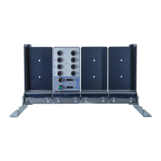
Page 101: Stand For 40Mm Aluminium Profile
The aluminium profile ist not contained in the delivery. Its length determines the maximum number of Irinos-Boxes, which can be mounted. A tap is required to cut a thread into the aluminium profile (typically M8; depending on profile). Irinos IR Users Manual © 2015 - 2016 Messtechnik Sachs GmbH, Germany... - Page 102 3. Optionally a protection cover can be fixed at the upper side of the stand. This allows protecting the Irinos-System against dripping fluids. Side view Example Irinos IR Users Manual © 2015 - 2016 Messtechnik Sachs GmbH, Germany...
-
Page 103: Cabling
Avoid cables which are longer than required. Especially avoid cable loops. o All measurement and ILink cables must be shielded properly. Irinos IR Users Manual © 2015 - 2016 Messtechnik Sachs GmbH, Germany... -
Page 104: Ethernet Cabling
1:1 or crossed Ethernet cables are used. By factory defaults, the DHCP-Server of the Irinos-System is activated. This is a good choice for a direct connection to Irinos IR Users Manual © 2015 - 2016 Messtechnik Sachs GmbH, Germany... -
Page 105: Ilink Cabling
Irinos-Box, the maximum cable length to the next Irinos-Box is 0,3m. o Please note that only one Irinos-Box containing an Ethernet- Irinos IR Users Manual © 2015 - 2016 Messtechnik Sachs GmbH, Germany... -
Page 106: Io-Bus Cabling
LED. If the hat / din rail version is used, the termination must be activated via one of its DIP switches. Irinos IR Users Manual © 2015 - 2016 Messtechnik Sachs GmbH, Germany... -
Page 107: Connecting Inductive Probes
ILink interface. For encoders with special pinning, this may be different. Only use the appropriate connectors for the incremental encoders. Irinos IR Users Manual © 2015 - 2016 Messtechnik Sachs GmbH, Germany... -
Page 108: Connecting Analogue Sensors
Connecting digital in- and outputs Connect all digital in- and outputs to the dedicated connectors or terminal blocks. Use protection caps for unused connectors. These are available separately. Irinos IR Users Manual © 2015 - 2016 Messtechnik Sachs GmbH, Germany... -
Page 109: Setup
Setup... -
Page 110: First Steps
The order of the measurement inputs and digital in- and outputs depends on the order of the boxes. The following figures provide some examples for Box addressing: Irinos IR Users Manual © 2015 - 2016 Messtechnik Sachs GmbH, Germany... - Page 111 System, since then no care must be taken when this Box is replaced. (The Irinos-Power supply can be placed at the the other side without affecting the addressing, since it is not part of the ILink communication system.) Irinos IR Users Manual © 2015 - 2016 Messtechnik Sachs GmbH, Germany...
-
Page 112: Network Configuration
192.168.3.100 to 192.168.3.254). No further network configuration is required. In delivery condition the DHCP-Server of the Irinos-System is activated. This is a good choice for a direct connection to a PC. Irinos IR Users Manual © 2015 - 2016 Messtechnik Sachs GmbH, Germany... -
Page 113: Irinos-Tool
Performing firmware updates. o Reading the content of the diagnostic memory (and saving it to a file). Further information is available in the documentation of the Irinos- Tool. Irinos IR Users Manual © 2015 - 2016 Messtechnik Sachs GmbH, Germany... -
Page 114: Web-Server
The web-server has been tested with various web- browsers. Because of the different interpretation of standards, it cannot be guaranteed with all browsers. 4 websites are available: Measurement (measurement values) Irinos IR Users Manual © 2015 - 2016 Messtechnik Sachs GmbH, Germany... - Page 115 Comparing the measurement values delivered by the Irinos- System to those shown in the measurement software. Network The website "Network" shows the configuration and status of the network connection to the PC: Irinos IR Users Manual © 2015 - 2016 Messtechnik Sachs GmbH, Germany...
- Page 116 Setup Inventory The website "Inventory" provides an overview of all Irinos-Boxes available in the Irinos-System. Further some detailed information is available about the Irinos-Boxes: Irinos IR Users Manual © 2015 - 2016 Messtechnik Sachs GmbH, Germany...
- Page 117 Number of available Digital Inputs digital inputs. Number of available Digital Outputs digital outputs. Diagnostic (Diagnostic memory) The website "Diagnostic" shows the contents of the diagnostic memories of all Irinos-Boxes: Irinos IR Users Manual © 2015 - 2016 Messtechnik Sachs GmbH, Germany...
- Page 118 Setup Irinos IR Users Manual © 2015 - 2016 Messtechnik Sachs GmbH, Germany...
- Page 119 Hour:Minute:Second: Millisecond Module 0x2800 Additional information for manufacturer support. Line Additional information Event Probe short circuit. for the event. Firmware-Version at Firmware-Version V0.4.0.1 the time the event occured. Irinos IR Users Manual © 2015 - 2016 Messtechnik Sachs GmbH, Germany...
-
Page 121: Measurement / Control Via Mscdll
Measurement / Control via MscDll... -
Page 122: Introduction
Therefore the Irinos-System can be used with standard windows installations. Special extensions, like for example realtime kernel extensions, are not required. In order to achieve this, all realtime data is buffered inside the Irinos- Irinos IR Users Manual © 2015 - 2016 Messtechnik Sachs GmbH, Germany... - Page 123 Bit I/Os and hardware status (see figure below). Packing and unpacking that data is done by the MscDll. The application is neither able nor required to influence this. Irinos IR Users Manual © 2015 - 2016 Messtechnik Sachs GmbH, Germany...
-
Page 124: Static Vs. Dynamic Measurement
Static vs. dynamic measurement The MscDll distinguishes between two types of measurement: Static measurement and dynamic measurement. Both can be used in parallel. Following a short introduction shall be given. More Irinos IR Users Manual © 2015 - 2016 Messtechnik Sachs GmbH, Germany... -
Page 125: Integrating The Dll / Configuration
Integrating the DLL / Configuration The steps necessary to integrate the MscDll into the measurement Irinos IR Users Manual © 2015 - 2016 Messtechnik Sachs GmbH, Germany... -
Page 126: Connecting To The Irinos-System
The connection remains active, until the application is closed. The following figure shows necessary steps for establishing a connection: Steps for "Establishing a connection with the MscDll" Irinos IR Users Manual © 2015 - 2016 Messtechnik Sachs GmbH, Germany... -
Page 127: Closing The Connection
A connection to the Irinos-System must always be closed before the application (measurement software) is closed. Otherwise an exception can occur. The following figure shows the steps necessary for closing the connection: Irinos IR Users Manual © 2015 - 2016 Messtechnik Sachs GmbH, Germany... -
Page 128: Static Measurement
The following figure shows the required steps for starting a static measurement: Irinos IR Users Manual © 2015 - 2016 Messtechnik Sachs GmbH, Germany... - Page 129 Since plenty of memory is available on a PC, it is good practice to allocate 1024 bytes of memory for a maximum of 256 measurement channels. The following table shows the buffer layout: Irinos IR Users Manual © 2015 - 2016 Messtechnik Sachs GmbH, Germany...
- Page 130 Using notifications is recommended, but not required. o The measurement values are first stored into an internal buffer of the MscDll. In order to copy them into the buffer of the application, Irinos IR Users Manual © 2015 - 2016 Messtechnik Sachs GmbH, Germany...
- Page 131 30 updates/s. The following table shows typical update rates for various combinations of send-period and "number of Irinos-Boxes", if no dynamic measurement is active: Irinos IR Users Manual © 2015 - 2016 Messtechnik Sachs GmbH, Germany...
- Page 132 Measurement / Control via MscDll Send- Update- Number of Internal Approxima period rate MscDll Irinos- Update- te number MscDll Boxes rate achievable updates/s measurem channel [ms] Updates/s Updates/s Updates/s Irinos IR Users Manual © 2015 - 2016 Messtechnik Sachs GmbH, Germany...
-
Page 133: Dynamic Measurement
Using position-triggered dynamic measurement, all measurement values are sampled simultaneously in pre-defined position-distances. This requires a measurement channel, which provides the position information. For example an incremental Irinos IR Users Manual © 2015 - 2016 Messtechnik Sachs GmbH, Germany... - Page 134 Therefore often time-triggered measurement can be used in such applications. Before starting a dynamic measurement, it must be defined. The following figure shows the typical steps for configuring, starting, running and finishing a dynamic measurement: Irinos IR Users Manual © 2015 - 2016 Messtechnik Sachs GmbH, Germany...
- Page 135 (0x22), a channel list is transferred to the Irinos-System. The channel list contains a list of all measurement channels, which shall be used for the dynamic measurement. 32 channels can be used at maximum. Irinos IR Users Manual © 2015 - 2016 Messtechnik Sachs GmbH, Germany...
- Page 136 Similar to the static measurement, all measurement values are stored as 32 bit integer values. f) The dynamic measurement is started using the function MSC_WriteCommand together with the opcode opcAT (0x31). This will Irinos IR Users Manual © 2015 - 2016 Messtechnik Sachs GmbH, Germany...
- Page 137 If an identical dynamic measurement is repeated, it is possible to omit the steps a) to d). The follwing figure shows the steps for repeating a dynamic measurement: Irinos IR Users Manual © 2015 - 2016 Messtechnik Sachs GmbH, Germany...
-
Page 138: Further Notes
- Dynamic measurement 2: opcDDM2 (0x51) und opcRDM2 (0x61) If two time-triggered dynamic measurements are executed simultaneously, the sum of the sample-rates is limited to 5.000 measurement values / s. Examples for valid sample-rates are: Irinos IR Users Manual © 2015 - 2016 Messtechnik Sachs GmbH, Germany... - Page 139 Irinos-Boxes involved. All Irinos-Boxes currently available support a sample period of 0,05ms = 50µs. Examples for valid sample-periods are: Irinos IR Users Manual © 2015 - 2016 Messtechnik Sachs GmbH, Germany...
- Page 140 100.000 measurement values per channel can be stored. Since the speed of reading the values depends on various factors, Irinos IR Users Manual © 2015 - 2016 Messtechnik Sachs GmbH, Germany...
-
Page 141: Buffer (Array) With Dynamic Measurement Values
All measurement values are stored as "32 Bit integer" values (little endian), independent of the data type of the respective measurement channel. Thus follows: o All buffers have the same size. Irinos IR Users Manual © 2015 - 2016 Messtechnik Sachs GmbH, Germany... - Page 142 All buffers have the same filling level, i.e. the filling level returned by the function MSC_GetPosition applies to all buffers of a dynamic measurement. Irinos IR Users Manual © 2015 - 2016 Messtechnik Sachs GmbH, Germany...
-
Page 143: Examples For Dynamic Measurement
The following examples show the use of the dynamic measurement. Together with the demo applications, these are a starting point for the implementation of the dynamic measurement into the Irinos IR Users Manual © 2015 - 2016 Messtechnik Sachs GmbH, Germany... -
Page 144: Example 1: Timer-Triggered Dynamic Measurement
It is known that the measurement takes about 2 seconds; an exact duration is unknown. Therefore the dynamic measurement must be started with a longer duration. 4 seconds are chosen. While the Irinos IR Users Manual © 2015 - 2016 Messtechnik Sachs GmbH, Germany... - Page 145 = MSC_AttachSubChannelBuffer(pDevice, opcRDM1, i, 20000*4, &buffer[i]); if (result != MSC_STATUS_SUCCESS) return -5; // Activate trigger ansiString = “#1#”; WriteCommandStr(opcAT, ansiString); if (ansiString != “#0#”) return -6; // An error occured: cancel Irinos IR Users Manual © 2015 - 2016 Messtechnik Sachs GmbH, Germany...
-
Page 146: Example 2: Position-Triggered Dynamic Measurement
The working piece is measured using two inductive probes. The incremental encoder is connected to measurement input T12, the inductive probes are connected to T4 and T5. Irinos IR Users Manual © 2015 - 2016 Messtechnik Sachs GmbH, Germany... - Page 147 // Setup data transfer channel for dynamic measurement values result = MSC_SetupExtendedDynamicChannel(pDevice, opcRDM1, 2, 1, NULL); if (result != MSC_STATUS_SUCCESS) return -4; // Allocate 2 buffers, each having a size of 720 * 4 Bytes = Irinos IR Users Manual © 2015 - 2016 Messtechnik Sachs GmbH, Germany...
- Page 148 If the incremental encoder crosses the index signal, the position of the incremental encoder is set to 0. The dynamic measurement now starts sampling the measurement values. Irinos IR Users Manual © 2015 - 2016 Messtechnik Sachs GmbH, Germany...
-
Page 149: Example 3: 2 Dynamic Measurements Simultaneously
4.000 samples/s, for the second one a sample rate of 1.000 samples/s is sufficient. The measurement channels T1, T2, T3 and T9 are required for the first working piece. Irinos IR Users Manual © 2015 - 2016 Messtechnik Sachs GmbH, Germany... - Page 150 // TriggerNo 1; channel list 1; dyn. measurement active; // number of samples: * = unlimited ansiString = “#1;1;1;*#”; WriteCommandStr(opcDDM1, ansiString); if (ansiString != “#0#”) return -103; // An error occured: cancel starting measurement Irinos IR Users Manual © 2015 - 2016 Messtechnik Sachs GmbH, Germany...
- Page 151 (ansiString != “#0#”) return -206; // An error occured: cancel starting measurement // Wait until the dynamic measurements are finished. do { result = MSC_GetPosition(pDevice, opcRDM1, &nSamplesDyn1); Irinos IR Users Manual © 2015 - 2016 Messtechnik Sachs GmbH, Germany...
-
Page 152: Bit I/O
8.10 Bit I/O The exchange of Bit I/O data is similar to the static measurement. The following figure shows the steps for the start of the Bit I/O data exchange: Irinos IR Users Manual © 2015 - 2016 Messtechnik Sachs GmbH, Germany... - Page 153 MscDll. In order to copy them into the buffer of the application, the function MSC_ReadStatic together with the opcode opcBIO (0x42) must be called (see following figure). This function must be called Irinos IR Users Manual © 2015 - 2016 Messtechnik Sachs GmbH, Germany...
- Page 154 After each update, the function MSC_RefreshChannel together with the opcode opcBIO (0x42) must be called in order to inform the MscDll about the update: Steps for "updating Bit-I/O data" Irinos IR Users Manual © 2015 - 2016 Messtechnik Sachs GmbH, Germany...
- Page 155 [69 .. 72 - [69 .. 72 - > "virtual"] > "virtual"] IR-TFV IR-INC IR-DIO -16- 73 .. 80 73 .. 80 IR-DIO -16- 81 .. 96 81 .. 96 Irinos IR Users Manual © 2015 - 2016 Messtechnik Sachs GmbH, Germany...
- Page 156 If for example 64 output bits are written, then 64 input bits will be read. If for example 128 output bits are written, then 128 input bits will be Irinos IR Users Manual © 2015 - 2016 Messtechnik Sachs GmbH, Germany...
-
Page 157: Error- And Diagnostics-Management
Bit I/O send- and receive- buffer (example for 128 Bits) 8.11 Error- and diagnostics-management The Irinos-System has various intgerated diagnostic mechanisms. The MscDll allows reading the operation status. Two categories are available: Irinos IR Users Manual © 2015 - 2016 Messtechnik Sachs GmbH, Germany... -
Page 158: Status Of Measurement Channels ("Hardware Status")
Typically the reason for this is a broken ILink cabling (broken cable, connector not fixed properly, ...). The manipulated value and the behaviour depend on the measurement channel type: Irinos IR Users Manual © 2015 - 2016 Messtechnik Sachs GmbH, Germany... - Page 159 Two possibilities are available for accessing the hardware status: 1. It can be updated continuously via a static data channel by the MscDll, like it is used for the static measurement values or the Bit Irinos IR Users Manual © 2015 - 2016 Messtechnik Sachs GmbH, Germany...
- Page 160 Steps for "reading the hardware status from a static data channel" 2. It can be readout manually by the application via the function MSC_WriteCommand e.g. at the end of a measurement sequence. Irinos IR Users Manual © 2015 - 2016 Messtechnik Sachs GmbH, Germany...
-
Page 161: Reading / Resetting The Event Status Of Irinos-Boxes
By clearing (deleting) an event, it is no longer set as "current Event" and it is no longer displayed via the status LED respectively the digit display . Please note: Irinos IR Users Manual © 2015 - 2016 Messtechnik Sachs GmbH, Germany... -
Page 162: Setting The Absolute Time For The Diagnostics Memory
MSC_WriteCommand together with the opcode opcSAbsT (0x3A). For longterm operation it is recommended to update the date and time once per day in order to adjust any inaccuracies of the internal clock. Irinos IR Users Manual © 2015 - 2016 Messtechnik Sachs GmbH, Germany... -
Page 163: Verifying The System Structure
(e.g. showing a warning message). The following figure shows the required steps for reading and comparing the system-string: Irinos IR Users Manual © 2015 - 2016 Messtechnik Sachs GmbH, Germany... -
Page 164: Tips Und Tricks
First it is required to read the number of Boxes using the opcode opcRIV (0x01). Afterwards further information can be requested for each of the available Irinos-Boxes using the opcode opcRMI (0x03). Both opcodes are used with the function MSC_WriteCommand: Irinos IR Users Manual © 2015 - 2016 Messtechnik Sachs GmbH, Germany... -
Page 165: Limiting The Number Of Static Channels
Two steps are required: a) All channels used for the static measurement must be defined via a channel list. Therefore the function MSC_WriteCommand together with the opcode opcWCL (0x22) is used. Irinos IR Users Manual © 2015 - 2016 Messtechnik Sachs GmbH, Germany... -
Page 166: License
If the MscDll is used with another hardware than the Irinos-System, license fees must be paid. Licenses are solely sold directly by Messtechnik Sachs GmbH. Irinos IR Users Manual © 2015 - 2016 Messtechnik Sachs GmbH, Germany... - Page 167 Measurement / Control via MscDll Detailed licensing information is provided in the legal notes section of this manual. Irinos IR Users Manual © 2015 - 2016 Messtechnik Sachs GmbH, Germany...
- Page 169 Troubleshooting and "first aid"...
-
Page 170: Troubleshooting And "First Aid" General Procedure
It may be necessary to formulate multiple problem descriptions. Gathering information Describe the situation before and after the problem occurred. The following questions may help: Irinos IR Users Manual © 2015 - 2016 Messtechnik Sachs GmbH, Germany... - Page 171 Especially when it is difficult to locate the problem, it is important to watch for little details. Sometimes a LED or a suspicious noise provides more and better information than the best measurement Irinos IR Users Manual © 2015 - 2016 Messtechnik Sachs GmbH, Germany...
-
Page 172: Diagnostic Events
Following those events are listed, which are relevant for practice: Event 1: System Description Common system event Type Information o System started Reason Diagnostics memory has been Irinos IR Users Manual © 2015 - 2016 Messtechnik Sachs GmbH, Germany... - Page 173 Stored in diagnostic Yes, can be disabled memory Event 12: ILink module detection error This error can occur only during Description the start-up phase of the Irinos- Irinos IR Users Manual © 2015 - 2016 Messtechnik Sachs GmbH, Germany...
- Page 174 Yes, can be disabled. application Stored in diagnostic Yes, can be disabled. memory Event 13: ILink communication error The ILink communication between Description the Irinos-Boxes has been disrupted. Type Error Irinos IR Users Manual © 2015 - 2016 Messtechnik Sachs GmbH, Germany...
- Page 175 Probe connected incorrectly, e.g. if an extension cable is used. -> Check the pinning If the problem is removed, the event is automatically cleared. Note èIn order to locate the defective Irinos IR Users Manual © 2015 - 2016 Messtechnik Sachs GmbH, Germany...
- Page 176 Yes, can be disabled application Stored in diagnostic Yes, can be disabled memory Event 24: Inc. encoder power error The power supply of one or Description multiple channels for incremental Irinos IR Users Manual © 2015 - 2016 Messtechnik Sachs GmbH, Germany...
- Page 177 Yes, can be disabled. application Stored in diagnostic Yes, can be disabled. memory Event 25: Inc. encoder application error Encoder signals were / are out of Description specification. Irinos IR Users Manual © 2015 - 2016 Messtechnik Sachs GmbH, Germany...
- Page 178 An input channel can be reset using the opcode opcSP (0x35). See reference manual for further details. Reported to the user / Yes, can be disabled. application Irinos IR Users Manual © 2015 - 2016 Messtechnik Sachs GmbH, Germany...
- Page 179 Event 28: Firmware update successful Description Firmware successfully updated Type Information Reported to the user / No, cannot be enabled. application Stored in diagnostic memory Yes, cannot be disabled. Irinos IR Users Manual © 2015 - 2016 Messtechnik Sachs GmbH, Germany...
- Page 180 Event 34: 24V output error The 24V supply for the digital in-/ Description outputs and the analogue inputs has been overloaded. Type Error o Load too high Reason / Solution Irinos IR Users Manual © 2015 - 2016 Messtechnik Sachs GmbH, Germany...
- Page 181 Cable to the I/O-Box has been removed. Reason / Solution o Defective IO-Bus cable -> Replace cable o Improper termination of the IO- Bus. -> Check termination Irinos IR Users Manual © 2015 - 2016 Messtechnik Sachs GmbH, Germany...
-
Page 182: Diagnostic Memory
The diagnostic memory can be accessed via the integrated webserver or the Irinos-Tool. The diagnostic memory is an important tool for detailed problem analysis, especially if events occur sporadically. Irinos IR Users Manual © 2015 - 2016 Messtechnik Sachs GmbH, Germany... -
Page 183: First Aid "Network Connection
PC. A working electrical connection is signalled by the "Link-LED" (IR- MASTER ) respecively the "Ethernet-LED" (integrated Master ). This LED must either be turned on or flashing. Irinos IR Users Manual © 2015 - 2016 Messtechnik Sachs GmbH, Germany... - Page 184 Network configuration of the Irinos-Tool e) Open the Windows configuration settings of the network adapter, which is connected to the Irinos-System. Open the settings for "internet protocol version 4 (TCP/IPv4)". Irinos IR Users Manual © 2015 - 2016 Messtechnik Sachs GmbH, Germany...
- Page 185 Copy the file Msc.cfg from the directory of the Irinos-Tool into the directory of the measurement application. In case this file already exists, it must be replaced. g) Start the application. The connection should now be established. Irinos IR Users Manual © 2015 - 2016 Messtechnik Sachs GmbH, Germany...
- Page 186 Troubleshooting and "first aid" Irinos IR Users Manual © 2015 - 2016 Messtechnik Sachs GmbH, Germany...
-
Page 187: Maintenance, Cleaning And Disposal
Maintenance, cleaning and disposal... -
Page 188: Maintenance
The cleaning work listed in the table below needs to be done regularly. In case the Irinos-System is used in an environment with extensive dirt, the intervals may need to be reduced. Irinos IR Users Manual © 2015 - 2016 Messtechnik Sachs GmbH, Germany... -
Page 189: Disposal
10.3 Disposal Dispose the Irinos-System and the accessories at appropriate recycling- or disposal stations. Contact your local authorities for further information. Do not dispose it in household waste. Irinos IR Users Manual © 2015 - 2016 Messtechnik Sachs GmbH, Germany... -
Page 191: Application Notes
Application notes... -
Page 192: Incremental Encoders 1Vpp Or Ttl/Rs422
Jerky movement due to mechanical tensions It is recommended to take this into account during the planning phase. If a jerky movement cannot be avoided, this must be Irinos IR Users Manual © 2015 - 2016 Messtechnik Sachs GmbH, Germany... -
Page 193: Interpolation (Only 1Vpp)
(patent applies). It corrects these deviations within the allowed value range (see limiting values in the specification section of the datasheet). Irinos IR Users Manual © 2015 - 2016 Messtechnik Sachs GmbH, Germany... - Page 194 Often the reason for a signal problem is a combination of these factors. Suggestions o Please observe the cut-off frequency of the incremental encoder. It can be found in the encoder datasheet. Irinos IR Users Manual © 2015 - 2016 Messtechnik Sachs GmbH, Germany...
-
Page 195: Power Consumption
The following table helps estimating the total power consumption. Please note that all values are guidelines. The actual power consumption may differ. Detailed information regarding the power consumption can be found in the respective datasheets. Irinos IR Users Manual © 2015 - 2016 Messtechnik Sachs GmbH, Germany... - Page 196 For most applications the additional power consumption for external loads is in the range of a few watts. Special care must be taken regarding loads switched via digital outputs, e.g. valves or lamps. Irinos IR Users Manual © 2015 - 2016 Messtechnik Sachs GmbH, Germany...
-
Page 197: Storing Data In The Non-Volatile Memory
System function Note of write operations Diagnostic memory 4,8 Millions Measurement channel Executed via the 200.000 configuration opcode opcWCC. Changing the IP Network configuration 200.000 settings. Firmware update 100.000 Irinos IR Users Manual © 2015 - 2016 Messtechnik Sachs GmbH, Germany... -
Page 199: Specifications & Dimensions
Specifications & dimensions... -
Page 200: Common Specifications
1 channel -> total: 10.000 samples/s 17 channels -> total: 170.000 samples/s 32 channels -> total 320.000 samples/s Synchronisation Simultaneous sampling of all measurement channels (also via multiple Irinos-Boxes) Irinos IR Users Manual © 2015 - 2016 Messtechnik Sachs GmbH, Germany... - Page 201 For example with IR-TFV max. 256 measurement channels. Maximum ILink cable length 20 m (total length from first to last Irinos-Box) ILink termination automatic Box addressing automatic Irinos IR Users Manual © 2015 - 2016 Messtechnik Sachs GmbH, Germany...
-
Page 202: Dimensions Irinos-Box
Labelling carrier for labelling the measurement channels and digital in-/outputs, appropriate for labels type Murrplastik ABB 17x9 (Order- No. Murrplastik: 86421020). 12.2 Dimensions Irinos-Box All dimensions are in mm. Irinos IR Users Manual © 2015 - 2016 Messtechnik Sachs GmbH, Germany... - Page 203 Specifications & dimensions Dimensions Irinos-Box (front side) Irinos IR Users Manual © 2015 - 2016 Messtechnik Sachs GmbH, Germany...
- Page 204 Specifications & dimensions Dimensions Irinos-Box (side view) Irinos IR Users Manual © 2015 - 2016 Messtechnik Sachs GmbH, Germany...
-
Page 205: Dimensions Power Supply Ir-Pu50
Specifications & dimensions Dimensions Irinos-Box (rear view) 12.3 Dimensions power supply IR-PU50 Alle dimensions are in mm. Irinos IR Users Manual © 2015 - 2016 Messtechnik Sachs GmbH, Germany... - Page 206 Specifications & dimensions Dimensions power supply (front view) Irinos IR Users Manual © 2015 - 2016 Messtechnik Sachs GmbH, Germany...
- Page 207 Specifications & dimensions Dimensions power supply (side view) Irinos IR Users Manual © 2015 - 2016 Messtechnik Sachs GmbH, Germany...
-
Page 208: Dimensions Front-Side Mounting Adapter Ir-Mffm-1
Specifications & dimensions Dimensions power supply (rear view) 12.4 Dimensions front-side mounting adapter IR-MFFM-1 Alle dimensions are in mm. Irinos IR Users Manual © 2015 - 2016 Messtechnik Sachs GmbH, Germany... - Page 209 Specifications & dimensions Irinos IR Users Manual © 2015 - 2016 Messtechnik Sachs GmbH, Germany...
- Page 210 Specifications & dimensions Irinos IR Users Manual © 2015 - 2016 Messtechnik Sachs GmbH, Germany...
- Page 211 Specifications & dimensions Irinos IR Users Manual © 2015 - 2016 Messtechnik Sachs GmbH, Germany...
- Page 212 Specifications & dimensions Irinos IR Users Manual © 2015 - 2016 Messtechnik Sachs GmbH, Germany...
-
Page 213: Index
29, 95, 96 - E - MscDll - N - Ethernet 68, 104 event status events Network configuration network interface - F - - P - Front-side mounting position-triggered Irinos IR Users Manual © 2015 - 2016 Messtechnik Sachs GmbH, Germany... - Page 214 26, 40 SPC system Static measurement 124, 128 Status LED Synchronisation system-string - T - termination time-triggered TTL / RS422 TTL/RS422 - W - Web-Server - X - XSync Irinos IR Users Manual © 2015 - 2016 Messtechnik Sachs GmbH, Germany...
Need help?
Do you have a question about the Irinos IR and is the answer not in the manual?
Questions and answers