Table of Contents
Advertisement
Available languages
Available languages
Quick Links
Ex II
Typ VS1
• E x II
• S c hutzart IP 66
• E xplos ions ges c hützter
optis c h/akus tis c her
S ignalgeber
• AT E X-bes c heinigt nac h
R ic htlinie 94/9/E G
• L auts tarker Mehrtonwec ker
• L eis tungs s tarke B litzleuc hte
• E x II
• P rotec tion c ategory IP 66
• E xplos ion-proof optic al
and ac ous tic
s ignalling devic e
• AT E X-c ertified ac c .
to direc tive 94/9/E C
• L oud multitone bell
• P owerful s trobe light
VS1 3.0
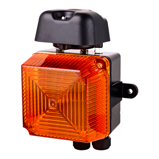
Anrufmelder optisch - akustisch
visual - audible secondary sounder
Verwendungs hinweis e
Anrufmelder optisch - akustisch Ex II
Der
ist speziell für die Ver-
wendung in explosionsgefährdeten
Industriebereichen konstruiert und
erlaubt das B etreiben in Gebäuden
und im Freien. Über einen S chiebe-
schalter lässt sich der
in die
folgenden B etriebsarten
schalten:
•
Anrufmelder optisch - akustisch Ex II
In dieser B etriebsart wird der
Ex II
mit einem Telefon
(mit W-Ader-Anschluss) zu sam -
mengeschaltet, um ein weiteres
akustisches und opt i sches S ig-
nal entfernt vom Telefon zu
erzeugen. Das akustische S ignal
endet mit dem R uf. Das opti-
sche S ignal bleibt während der
R ufpausen bestehen (R ufpau-
senüberbrückung). Das op tische
S ignal endet ca. 4 s nach dem
letzten R uf.
Die S peisung der optischen und
akustischen S ignale erfolgt aus
dem 230 V Netz. Angesteuert
werden die S ignale durch die
R ufwechselspannung. B ei Aus-
fall des Netzes erfolgt keine
S ignalisierung.
•
S ignalmelder
In dieser B etriebsart werden
durch das Anlegen des 230 V
Netzes
die akustischen und
optischen S ignale erzeugt.
Montage
Ex II
Der
ist für die Wand-
und
Deckenmontage geeignet.
Die Anbaumaße sind dem Maßbild
(siehe „Maßbild") zu entnehmen.
B efestigungselemente und Unter-
grund müssen das Gewicht des
Gerätes (ca.1,5 kg) tragen können.
Ans c hließen
Das Anschließen und Einstellen
des Gerätes darf nur durch unter-
wiesenes Fachpersonal erfolgen.
Es sind die Vorschriften und Hin-
weise des jeweiligen Landes zum
Applic ation Notes
visual - audible secondary sounder
The
especially con-
ceived for use in industrial hazar-
dous areas, allowing operation in
industry buildings and outdoors.
The DIP switch of the Ex II
Ex II
be
used
to the following operating modes:
•
Additional Telephone S ignalling
Device
For this operating mode the
telephone (with a W conductor)
to generate a further acoustic
and optical signal away from the
telephone. The ringing ends the
acoustic signal. The optical sig-
nal remains during the ringing
pauses (ringing pause bridging).
The optical signal ends approx.
4 sec. after the last ring. The
optical and acoustic signals are
supplied from the 230 V line. The
ringing alternating current is
used for controlling the signals.
In case of a loss of line voltage
there will be no signalling.
•
S ignalling Device
In this mode the acoustic and
optical signals are generated
upon connection to the 230 V
line.
Mounting
The Ex II is suited for wall
and ceiling mounting. R efer to the
dimensional drawing for the moun-
ting dimensions (refer to figure
„Physical dimensions"). B oth the
fasteners and the mounting surfa-
ce must be able to carry the weight
of the device (~1.5 kg).
C onnec ting
Only especially educated profes-
sional personnel may connect and
adjust the device. The rules and
regulations of each country regar-
ding connections to the public tele-
phone network or private branch
exchanges must be observed.
is
can
to
switch the device
Ex II is connected with a
1
Advertisement
Table of Contents

Summary of Contents for auer Ex II VS1
- Page 1 Anrufmelder optisch - akustisch Ex II visual - audible secondary sounder Typ VS1 Verwendungs hinweis e Applic ation Notes Anrufmelder optisch - akustisch Ex II visual - audible secondary sounder especially con- ist speziell für die Ver- ceived for use in industrial hazar- wendung in explosionsgefährdeten dous areas, allowing operation in Industriebereichen konstruiert und...
- Page 2 Anschalten öffentliche im S chiebeschalter muss in der zu lesen. B ei eventuellen S chäden Telefonnetz bzw. an private Neben- Po si tion „Telefonzweitmelder“ und Ansprüchen gelten die „Allge- stellenanlagen zu beachten. stehen (siehe „Einstellen des meinen Lieferbedingungen für Er- Nachfolgende Anschluss- und Ein- S chiebeschalters“).
- Page 3 The following regulations regarding work. The left contact in the DIP read carefully. In case of any d ama- connection and adjustments must switch must be in the position ge and liabilities the latest version be obeyed: The rules and regula- „Telephone S ignalling Device“...
- Page 4 Klemmbelegung / Termination Einstellen des Schiebeschalters / Setting the DIP switch Stellung Betriebsart Position Operating Mode Telefonzweitmelder Telephone Signalling Device Signalmelder Signalling Device Stellung Melodie Position Melody Schutzerde / Protective earth Dreiton 16,6 Hz Three-tone Dreiton 50 Hz Three-tone Netzspannung / Power connection Dreiton 120 ms ein / 50 ms aus...
- Page 5 Hersteller / Anschrift J.Auer GmbH Manufacturer / Factory address Perfektastr. 102 Fabricant / Adresse A-1230 Wien Geschäftsfrührer: Dipl. Ing. Michael Auer Managing director / Direction Gérant / Gerente: ............(Name, Vorname / name, prename / apellido, nombre) Wien 20.09.2010 ........
- Page 6 Fortschritt dienen, sind jederzeit mög- serving technical progress without further lich. notice. J. Auer Fabrik Elektrischer Maschinen Gesellschaft m. b. H Änderungen und Irrtum vorbehalten S ubject to alterations or errors Perfektastr. 102 Phone (00431) 813 82 20 http://www.auer-signal.com A-1230 Wien Telefax (00431) 815 99 51 e-mail: o ce@auer-signal.com...


Need help?
Do you have a question about the Ex II VS1 and is the answer not in the manual?
Questions and answers