Advertisement
Quick Links
Advertisement

Summary of Contents for DINDAN 14ACU/005
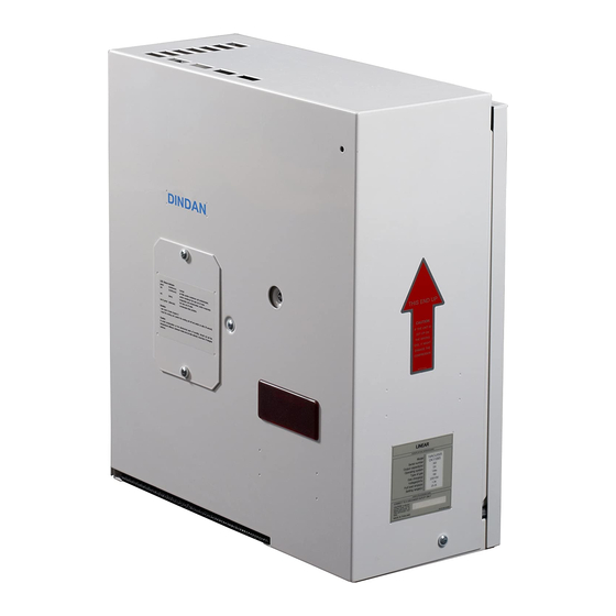
- Page 1 Enclosure cooling unit Model 14ACU/005 User's guide...
- Page 2 Authorized Service Center THAILAND : Dindan Technical Co.,Ltd. 27 Soi LuanJerAnuSorn 2 Sukhumvit Rd. Bangna Subdist., Bangna Dist., Bangkok 10260 Thailand Tel : +662 753 4212 Fax : +662 753 4211 E-mail: dindan@dindan-tech.com Website: www.dindan-tech.com VIETNAM : Space Cooling Co.,Ltd.
-
Page 3: Table Of Contents
Content Page 1. Over view 2. Specifications 3. Notification 4. Technical information 9-10 5. Installation 11-19 6. Maintenance 7. Fault Indication 8. Assembly and part number... - Page 4 Introduction Cooling unit for control cabinet is used for diminishing internal heat by providing cool air to the control cabinet that can protect sensitive equipment It is specially designed to resist surrounding temperature as high as 40-50 C and can function well in any factories including those with intensive dust, particles and oil mist or with high acidity.
-
Page 5: Over View
1. Over view 14ACU/005... - Page 6 Main controller (Hiprosent control) Evaporator fan Compressor Evaporator coil LED status display Condensor coil Temperature display Condensor fan Drain pan Filter Temperature setting Switch on-off Hiprosent control Main Controller box...
- Page 7 HIPROSENT CONTROL (EGS033-2) 1 2 B C 7 8 5 6 220V 50/60Hz Main connection from 10A BREAKER supply by Customer Control and Monitor A1 = Main Controller A2 = Temperature Adjustment A3 = LED compressor's status A4 = LED operating status A5 = LED Hi-Lo Voltage A6 = Socket for Output Alarm (not appropriate with Cooling Unit) Cable and signal...
-
Page 8: Specifications
2. Specifications Characteristics (under normal operating condition at ambient temp. +35 14ACU/005 Model Capacity W. Installation type panel Input single-phase (V.) 220V+20% / -15% frequency (Hz.) 50/60 current (A.) 1.83 Compressor hermetic type reciprocate torque start type refrigerant type 134a lock rotor (A.) - Page 9 Installation Plate & Templet for cutting Area View From Outside of Cabinet 14- 3.2 Drill Cutting Area 185 mm. 19.7 384 mm.(width) Warm Air (REAR VIEW) (LEFT VIEW) (FRONT VIEW) Return Air Warm Air Socket plug for Special holder Cold Air Ambient Air In Fasten M6x20mm.
-
Page 10: Notification
3. Notification • Before, drilling, and cut. should use clean dry cloth, or the inventory doesn’t lead the electricity, covers the equipment for protects iron dust touches the electrical equipment while installing. (In case of machine still operate.) • Cooling unit should be installed in the good circuration area •... -
Page 11: Technical Information
General Condition Storage: Cooling unit should be stored at temp not exceeding 70 Transportation: This type of cooling unit can't be laid down horizontally. Installation: It shall be installed in vertical direction only (please see figure below) INCORRECT CORRECT Disposal of damaged Cooling Unit As its refrigeration system contain Refrigerant and lubricating oil for compressor, in order to protect environment, these substances should be disposed of properly or other under direction given by distributor. - Page 12 Refrigeration Cycle Condenser Filter Compressor dryer External Internal Cap.tube Evaporator Drainage Drainage of condensed water from cooling system shall be done by inserting drain tube under drainpan (see page 18) and trying not to left it twisted. Make sure, the other end of drain tube is not lower than water level in the container, in order to avoid water reflux Drain tube Drain tube...
-
Page 13: Installation
5. Installation Accessories for 14ACU/005 Items Quantity Cooling unit User's guide & Warranty card Socket plug Socket plug base plate Special holder Foam gasket Air filte Socket plug cover (circle) Installing plate 3/8'' Drain Tube (200 cm.) 3 x 1 Sq.mm VCT power cord. (200 cm.) - Page 14 Installation procedure 1. Remove Installation plate B (front plate) from Installation plate A (back plate) Screw M4x10 mm. Installation plate B (front plate) Installation plate A (rear plate) 2. Align installation plate(rear plate) in the position to be installed.
- Page 15 3. Layout 1-14 positions for drilling and cutout along the dot line with Jigsaw 185 mm. 4. Cover eqipments inside cabinet with clean and dry cloth,and cover with paper boxes at position will be drilled and cutted in order to prevent metal scrapt falling in cabinet.
- Page 16 5. Drill and cut the holes and area as be pointed out from installation plate. 6. Chamfer the cutted edge and paint rust proff colour.
- Page 17 7. Socket plug Installation 7.1 Put the cable in the socket plug and screw. 7.2 Put the socket plug and Socket plug base plate in the position and screw it Installation plate A (rear plate) socket plug Socket plug base plate 3 x 1 Sq.mm.
- Page 18 9. Install the Installation plate B (front plate) to Installation plate A (rear plate) Installation plate A (rear plate) Installation plate B (front plate) 10. Install the socket plug cover. socket plug cover Fiber washer Self tapping screw 1/8'' x 3/8''...
- Page 19 11. Attach the foam gasket to the installation plate and fasten the special holders on it and then hang the cooling unit on this holders, fasten another 2 screws M6 x 20 mm. at the bottom of the cooling unit. Special holders foam gasket Installation plate and it foam...
- Page 20 13. Install the draining tube by the illustrature below Tire with 6” CABLE TIE Fixed with 1/2” CABLE CLAMP Fixed with 1/2” CABLE CLAMP 3/8” Draining tube Water level Tank Illustrate of drainage wiring Beware: Avoid dipping draing tube below than water level which be clogged its drainage 14.
- Page 21 Air diverter installation(In the necessary case) 1. Divert air down Turn the air diverter to blow air down as shown below the drill and fix it. 2. Divert air to left and right Turn air diverter to left or turn air diverter to right Drill and fix the diverter as shown below Illustrate diverting the air to left Illustrate diverting the air to right...
-
Page 22: Maintenance
6. Maintenance Maintenance of DINDAN cooling unit can be simply done by giving care to the air filter and condensor coil not to be clogged up. The cleaning interval for the air filter depends on how dirty it is of the area where it is installed. -
Page 24: Assembly And Part Number
8. Assembly and part number ITEM DESCRIPTION PART NUNMBER Qty. PART AVAILABLE main casing drain pan condenser coil evaporator coil servo fan 6'' EP-03-012 servo fan 4'' EP-03-102 compressor EP-04-101 control board XEE-22-011 filter CR-15-102...
Need help?
Do you have a question about the 14ACU/005 and is the answer not in the manual?
Questions and answers