Table of Contents

Summary of Contents for W&H 154CE
- Page 1 MODEL 154 & 154CE HAVE DIFFERENT CHAINS AND SPROCKETS! When in doubt on what sprockets you have, count the teeth and give us a call! Wrong parts will give you a headache! customerservice@williamsnhussey.com 800-258-1380 or local 603-732-0219...
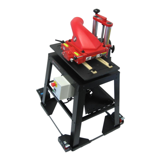
- Page 2 MODEL 154CE Single Phase, 240V, AC Shown with optional mobile base Manual # OM-981 Revision 4 – October 2018...
- Page 3 Williams & Hussey www.williamsnhussey.com Contact Information Williams & Hussey Machine Co., Inc. 105 State Route 101A, Unit 4 Amherst, NH 03031 603-732-0219 (local) customerservice@williamsnhussey.com (e-mail) 800-258-1380 (toll free) williamsnhussey.com (website) 603-732-4048 (fax) Business Hours: Monday – Friday 8:00 am – 4:30 pm EST THANK YOU for purchasing a Williams &...
-
Page 4: Warranty Information
Williams & Hussey Toll Free: 800-258-1380 WARRANTY INFORMATION Molder – 7 Year Limited Williams & Hussey Machine Co., Inc. warrants its molders for a period of seven years from the original date of purchase. WHAT IS COVERED? The warranty covers any defects in workmanship or materials. WHAT IS NOT COVERED? The warranty does not cover damage due to;... - Page 5 NOTE: A plug is NOT supplied with our molder. Because of plug receptacle variations we do not include this with the molder purchase. Purchase the proper plug and follow the manufacturer’s instructions for proper installation. Model 154CE Specifications Feed Type...
-
Page 6: Safety Checklist
Williams & Hussey Toll Free: 800-258-1380 Feel free to contact us by phone, fax, e-mail, or visit our website for molders, accessories, replacement parts and technical service. Our molders come with a lifetime guarantee of technical assistance! SAFETY CHECK LIST We encourage ALL operators of Williams &... - Page 7 Williams & Hussey www.williamsnhussey.com PREPARING TO USE THE MOLDER Steps 1-13 on pages 6-8 should be followed every time the molder is used. Understanding the molder and how to use it properly will ensure your safety, cut down on maintenance issues, and give your stock an excellent finish.
- Page 8 Williams & Hussey Toll Free: 800-258-1380 feel the “catch”, its now attached safely. DO NOT use the molder without the chip extractor safely attached! KNIFE ATTACHMENT – The molder requires (2) knives, attach the knives using (1) screw for each hole. The molder requires (2) knives (1 set) and screws to hold the knives safely in place.
- Page 9 Williams & Hussey www.williamsnhussey.com When molding, the head scale setting must be set to within 3/16” of the height of the stock entering the molder, compensating for any sub plate thickness. This setting will provide proper roller tension. NOT setting the head at the correct height is not safe. KNIFE CLEARANCE –...
- Page 10 Williams & Hussey Toll Free: 800-258-1380 HOW TO MOLD “SIZE” STOCK – See page 6, #1 SUB PLATE USE A sub plate made of knife millable material is recommended to be used at all times, except when using the optional elliptical jig. The GS-2-1 Guide System included in your molder package has a ½”...
-
Page 11: Operational Tips
Williams & Hussey www.williamsnhussey.com SETTING THE SCALE FOR SINGLE OR MULTIPLE PASSES The “0” on the yellow scale references the top of the GS-2-1 guide system ½” sub plate. Insert stock after head setting has been determined. Full pass cut example: ¾” Stock, set scale at ¾” achieving a finished profile. Multiple pass example: ¾”... - Page 12 Williams & Hussey Toll Free: 800-258-1380 MOLDING TECHNIQUES When making guides for molding applications we recommend running a test piece through, top and bottom before cutting finished pieces. Store guides along with the knives for future use. MOLDINGS THAT REQUIRE TOP & BOTTOM CUTS Crown Top &...
-
Page 13: Knife Sharpening
Williams & Hussey www.williamsnhussey.com SPECIAL GUIDE SET UP & KNIFE SHARPENING “V” BLOCKS The deepest cut that can be made on the molder is ¾”. If your depth of cut is greater than ¾” and you’re running straight molding a “V” block maybe your solution. - Page 14 Williams & Hussey Toll Free: 800-258-1380 CONSTANT RADIUS MOLDING The molder has the capabilities to cut constant radius molding. A constant radius means the radius does not change. A changing radius will require the EJ-92 Elliptical Jig. When molding constant or changing radius profiles the deep cut of the profile normally is on the open side of the molder.
-
Page 15: Helpful Tips
Williams & Hussey www.williamsnhussey.com Our EJ-92 Elliptical Jig is required. RAISED PANEL MOLDING NOTE: Panel must always have 9” for rollers to engage Our in stock panel knives are designed to produce a ¼” tongue on stock sizes ¾” or ”. - Page 16 Williams & Hussey Toll Free: 800-258-1380 PLANING The planing operation removes excess wood from rough lumber to create a uniform smooth surface. Plane rough lumber on all (4) sides until you reach the dimensional wood stock size. The amount of stock removed in one pass is dependent on the density of the wood (relative hardness), how wide the cut is, and the moisture content of the stock.
- Page 17 Williams & Hussey www.williamsnhussey.com WIDE BOARDS Our molders are open ended allowing stock to cut wide boards such as base boards and raised panel doors. Wide stock cuts may need support from the open ended side. Below are some guidelines to follow for this application. HELPFUL TIPS ●...
-
Page 18: Troubleshooting
Williams & Hussey Toll Free: 800-258-1380 TROUBLESHOOTING CHATTER - Chatter marks are irregularities in the finish quality of the surface of the wood. They can be evenly spaced or randomly distributed. Chatter marks are caused by vibration. Below is a list of possible causes of vibration. ●... -
Page 19: Feeding Problems
Williams & Hussey www.williamsnhussey.com FEEDING PROBLEMS 1. The stock stops but the feed-rollers continue to turn. This is a traction or friction problem. ● Make sure the stock is not binding in the guides. ● Make sure the stock is of consistent width. Sizing stock is recommended. ●... - Page 20 Williams & Hussey Toll Free: 800-258-1380 REMOVING FEED ROLLS If axles are removed easily they can be reused. In some cases the P-122 short axle will not remove easily, mainly because thread locker has been used. If you have difficulty removing the P-122 short axle you will need to use a hack saw to cut it, in this case you will not be able to reuse the feed roll.
- Page 21 Williams & Hussey www.williamsnhussey.com INSTALLING FEED ROLLS 1. Follow Steps 1-5; Removing Feed Rolls. 2. When installing the axles the feed roll should be inside the swing arm casting. NOTE: Proper placement of axles and orientation of swing arms is critical. Refer to illustration below. 3.
- Page 22 Williams & Hussey Toll Free: 800-258-1380 REMOVING THE P-511 REV A GEAR BOX, COMPLETE, ASSEMBLY Follow these instructions for removing the gear box. The gear box is composed of the (3) gear assemblies. If you are experiencing feed function difficulties a part may need to be replaced. 1.
- Page 23 Williams & Hussey www.williamsnhussey.com 11. Reassemble gear box. ● P-502 assembly ● P-503 assembly ● Align the slot in the P-115 plug bushing by looking through the hole of where the P-143 1/8” dowel pin goes. Tap in dowel pin until the pin is flush with the outside of the gear box housing.
- Page 24 Williams & Hussey Toll Free: 800-258-1380 EXPLODED VIEW 154CE MOLDER...
- Page 25 Williams & Hussey www.williamsnhussey.com EXPLODED VIEW FEED ROLL ASSEMBLIES P-137 P-122 P-137 P-224 P-111 54-15 54-15 P-123 54-15 54-15 P-122 P-137 P-100 P-137 P-124 P-111 P-123...
- Page 26 Williams & Hussey Toll Free: 800-258-1380...
-
Page 27: Shaft Assemblies
Williams & Hussey www.williamsnhussey.com SHAFT ASSEMBLIES Holes to be drilled at assembly Hole to be drilled at assembly... - Page 28 Williams & Hussey Toll Free: 800-258-1380 MODEL 154CE PARTS LIST Item # Description 54-1 REV A Bed, Machine, Painted 54-10 Arbor 54-14 Pin, Axis, Finished 54-15 Screw, Pivot 54-16 Screw, Rest 54-18 Cap, Matte Black 54-2 REV A Head, Painted...
- Page 29 Williams & Hussey www.williamsnhussey.com Breakdown of assemblies on next page. MODEL 154CE BREAKDOWN OF ASSEMBLIES PARTS LIST Parts can be ordered as individual items or by the assembly. Item # Description Swing Arm, Infeed, Assembly (includes) 54-505 P-100 Swing Arm, Infeed...
- Page 30 Williams & Hussey Toll Free: 800-258-1380 MODEL 154CE BREAKDOWN OF ASSEMBLIES PARTS LIST Parts can be ordered as individual items or by the assembly. Item # Description Gear Box, Assembly, Complete (includes) P-511 REV A P-101 Housing, Gear Box, Painted Bushing, Bronze, 7/16”...
Need help?
Do you have a question about the 154CE and is the answer not in the manual?
Questions and answers