Table of Contents
Advertisement
Quick Links
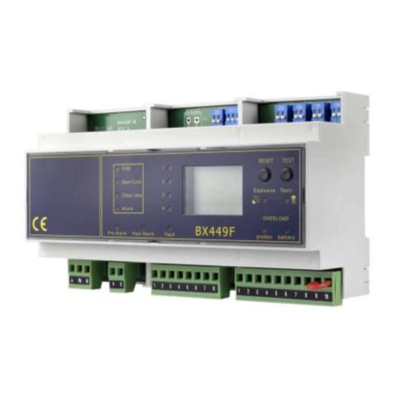
Din omega modular Gas/Fire control unit
With a
maintenance
BEINAT S.r.l. always attentive to the needs of the market and new technologies, has overhauled a previous
versatile control unit, BX449F, for GAS and/or FIRE detection for industrial applications.
sensors to detect: Toxic / Explosive Gases, Oxygen, and to detect fire principles.
Gas detection
The control unit has two danger levels:
1st LEVEL, pre-alarm. This is set at 13% of L.E.L. (200ppm) for all sensors.
2nd LEVEL, main alarm. This is set at 20 % of L.E.L. (300ppm) for all snsors.
To facilitate event readings, the control unit has a front panel with 4 LEDs indicating which probe is currently being
monitored in rotation, and a display showing the gas concentration measured on each pass.
GAS configurations
Connection from 1 to 4 conventional sensors, for different types of GAS up to max 4 sensors, 1 for each zone.
Fire detection
To the BX449F you can connect up to 5 fire detectors per each zone, either temperature or optical smoke detectors,
through a balanced line:
Optical smoke detectors, Temperature, Velocimetric temperature
The control unit's microprocessor checks the detectors and connection line efficiency, open or short-circuited.
When the sensors detect a fire, theyl switch the proper relay.
FIRE configurations
Each zone can be connected up to a Max 5 sensors, even mixed, Smoke or Temperature, for a total Max of 20.
Automatic recognition of the type of probe connected, be it GAS OR FIRE.
Configurations Mixed GAS FIRE
For each zone assigned, the detection of only GAS or FIRE can be connected without distinction
OXYGEN configurations
When the operation is selected to detect OXYGEN, other types of sensor cannot be connected.
OXYGEN ALARM for <Oxygen deficiency and> Oxygen Excess
For oxygen pre-alarm and main alarm levels, see references on page 5.
Maintenance TEST.
With special measures, the function can be enabled to exclude the alarm relay for a maximum duration of 60
minutes. This allows the technician to perform all functions without having to interrupt the gas flow or activate sirens
Important: Assembly / maintenance of the appliance must be carried out by qualified personnel
and in accordance with applicable laws and regulations.
The manufacturer assumes no responsibility for the use of products that have to comply with
particular environmental and / or installation standards.
Important note
Before connecting the equipment, it is recommended that you read the instruction manual carefully
and keep it for future reference. It is also recommended to perform the electrical connections
correctly as per enclosed drawings, observing the instructions and the Standards.
N.B. Refer to the documentation in all cases where the symbol is on the side
Installation
and user guide
m
progra
I N S TA LL
I N S A F E
AREA, NO ATEX
4 Conventional zones
BX449F
To which can connect
CONFORMITY
Conforme EN 60079-29-1
Reports issued by Eurofin Italia
Electric connections also available on
Channel: Beinat gas solutions
Belonging to
V3
EN 50270
EN 45544-1-3
EN 61010-1
Advertisement
Table of Contents

Summary of Contents for Anie BEINAT BX449F
- Page 1 Belonging to Din omega modular Gas/Fire control unit 4 Conventional zones BX449F With a maintenance progra BEINAT S.r.l. always attentive to the needs of the market and new technologies, has overhauled a previous versatile control unit, BX449F, for GAS and/or FIRE detection for industrial applications. To which can connect sensors to detect: Toxic / Explosive Gases, Oxygen, and to detect fire principles.
- Page 2 Precautions CHECK the integrity of the unit after having removed it from the box. Check that the data written on the box correspond to the type of gas used. When doing the electrical connections, follow the drawing closely. Any use of the detector for purposes other than the intended one is considered improper, and as a result of which BEINAT S.r.l.
- Page 3 Probe Sensor Degree Suitable for Range Output Precis. Calibration Relay Protec. Zone Detected Working Automatic SG500 C a t a l y t ic I P 3 0 Dom estic Use C H 4 - L P G 0÷ 10 0% L EL 4÷20 mA ±5 %...
- Page 4 Control unit from 1 to 4 conventional sensors BX449F Rev. 3 Instruction manual {a} OVERVIEW - Power supply 110/240 VAC - Controls up to 4 remote sensors, referred to Gas - Manages explosive and toxic gases. - Controls up to 20 remote sensors, referred to Fire - Manages smoke and temperature sensors - Manual alarm managed by remote button - Various possibilities of parameter configuration...
-
Page 5: Reset Button
3) Group of four double switches to select sensor and type of gas. DIP-SWITCH Sensor 1 - DIP-SWITCH Sensor 2 - DIP-SWITCH 3. Sensor 3 - DIP-SWITCH Sensor 4 Setting the first switch of each group to ON or OFF enables or disables the corresponding input. Setting the second switch of each group to ON or OFF switches to detect from explosive gas to toxic. - Page 6 6) TOXIC GAS LED selection . Turning on, this LED indicates that the corresponding input is configured to detect toxic gases. 7) EXPLOSIVE GAS LED selection . Turning on, this LED indicates that the corresponding input is configured to detect explosive gases. WARNING! The flashing of this LED can also indicates the presence of under/over range entering the corresponding input.
- Page 7 16) External manual alarm button. The control unit is designed to be connected to a manual alarm button. Pressing the button the control unit will go directly into alarm even when it is in programming or warm up status; Closing all the auxiliaries connected to it. When pressed, BTN appears on the display and turns red.
-
Page 8: Electrical Connection
{c} OPERATING INSTALLATION INSTRUCTIONS WARNING! The installation parameters modification must be performed by qualified personnel Be sure to disconnect the controller from the power supply before making changes to the connections ELECTRICAL CONNECTION Fire Main Alarm Power supply Pre-A larm GAS Main Alarm Fault 110/240 VAC... - Page 9 FIRE DETECTORS SERIES "NORMAL" 12 V Optional End of line resistance 1K2 End of line resistance 1K2 FIRE DETECTORS SERIES "ECO" 12 V Optional End of line resistance 1K2 The signal terminal block for the FIRE detection (previous figure) is composed as follows: - Terminal 1 and 2: Optional back-up battery connectione.
- Page 10 ACTIVATION AND DEACTIVATION OF THE SENSORS Through Micro switches on the control unit can enable or disable the 4 Zones. You can connect up to 4 sensors GAS (1 for each zone) Or, you can connect up to 20 FIRE detectors (5 for each zone) Mixed connections Gas Fire In the configuration Mixed Gas Fire every single zone can be connected indistinctly with: only GAS...
- Page 11 Switch 1 - the main alarm relay Working Mode. In the (impulse) position, the relay remains closed for 3 seconds, and then disenergizes afterwards. In the OFF (continuous) position, the relay remains closed until the RESET button is pressed. Switch 2 – Alarm logging maintenance, reserved for toxic gases By setting the micro-switch to ON, the device WILL LOG the alarm, maintain the relay closed, and the main alarm LED will blink, until the RESET button is pressed.
- Page 12 After making all the connections and configurations, the system can be powered WARNING! > This control unit is NOT built for installation in ATEX classified areas > To meet the requirements as a control unit according to the standard EN 60079-29-1: 2016, the DIP switches on the control unit must be set to: SW2.1: ON, SW2.2: OFF, SW3.2: ON, SW4.2: ON.
-
Page 13: H} Troubleshooting
{g} WORKING CONDITIONS Depending on the input signal of the remote sensors, the control units can be found in the following working condition: NORMAL MODE: the control unit receives a signal from the sensors corresponding to a gas level between 0% and 8% of LEL for explosive gases and between 0 ppm and 120 ppm for toxic gases. - Page 14 Explosive gas detection diagram Toxic gas detection diagram Fault zone Fault zone Over range area Over range area 16 ,8 16 ,8 Linear +/-5% Linear +/-5% 14 ,4 14 ,7 10 ,4 10 ,4 Under range area Under range area Fault zone Fault zone Programma...
- Page 15 {j} STORAGE Temperature operating range: -10° C to + 60° C Humidity operating range: 0 ÷ 90% RH not condensed Pressure operating range: 800 ÷ 1100 hPa {k} CONTAMINANTS Not applicable to the control unit. For the remote sensor, refer to the remote sensor user manual {l} AUTOMATIC RESET The pre-alarm relay state is automatically reset when the concentration drops below the pre-alarm threshold.
-
Page 16: Electrical Connections
{r} INSTALLATION EXAMPLES ELECTRICAL CONNECTIONS NOTE! All relays are voltage free WARNING. Before connecting to the mains power, ensure the voltage is correct. Carefully follow the instructions and the connections according to Regulations in force, keeping in mind that the signal RESET TEST FIRE... - Page 17 Sensors terminal block for GAS detection In this diagram they are connected three probes GAS and one of fire. N.B. at each input you can connect: 1 GAS sensor,1 Group sensors fire from 1 to 5 max RESET TEST FIRE 2 3 4 Open Line Explosive...
- Page 18 Installing and positioning the control unit The BX449F control unit belongs to group II and must be installed in a safe area; Outside the ATEX zone, however, not in boiler rooms or engine room. The control unit must be accessible and visible to the user. The BX449F control unit is a device suitable for being installed on the wall, or on an electrical panel using the special bracket, optional, on request.
- Page 19 Turn On 1) Apply power using the proper external switch. This switch should be fitted with protection fuses. 2) You will notice that some LEDs will light up in turn for about 20”. N.B. Make sure all leds are working. 3) The display will start the COUNT DOWN of about 90 seconds (warm up).
-
Page 20: Disposal Of Old Electrical & Electronic Equipment
INSURANCE. This device is insured by the SOCIETÀ REALE MUTUA for the PRODUCT'S GENERAL LIABILITY up to a maximum of 1,500,000.00 EURO against damages caused by the device in case of failures in functioning. WARRANTY. The warranty term is 3 years from manufacturing date, in agreement with the following conditions.
Need help?
Do you have a question about the BEINAT BX449F and is the answer not in the manual?
Questions and answers