
Subscribe to Our Youtube Channel
Summary of Contents for FMC Technologies Smith Meter microFlow.net Gas
- Page 1 Electronic Gas Flow Computer Smith Meter ® microFlow.net ™ Operations Manual Issue/Rev. 0.0 (2/10) Bulletin MNFG003 The Most Trusted Name In Measurement...
- Page 2 FMC Technologies Measurement Solutions, Inc. FMC Technologies Measurement Solutions, Inc. will not be held responsible for loss of gas or for damage of any kind or from any cause to the person or property of others, or for loss or profit, or loss of use, or any other special,...
-
Page 3: Table Of Contents
Table of Contents Section I – Introduction ............................1 Product Description ..............................1 How To Use This Manual ............................2 Section II – Display and Controls ...........................3 microFlow.net Gas Display and Controls ......................3 Power Up ................................4 Section III – Run Mode ............................8 Run Mode ................................8 Overview ................................8 Resetting/Starting a New Batch ...........................8 Stopping the Flow Using the Keypad ........................8... -
Page 5: Section I - Introduction
Section I – Introduction Product Description The Smith Meter microFlow.net Gas is a micro-processor based single meter, single product electronic flow computer ® ™ instrument that monitors continuous gas flow applications. The unit can operate either as a stand-alone instrument or part of a SCADA system. -
Page 6: How To Use This Manual
Section I – Introduction How To Use This Manual This manual is to be used as an operators guide for the microFlow.net Gas. This manual is divided into the following sections: Introduction, Display and Controls, Run Mode, Program Mode, Diagnostics, and Index. The “Display and Controls”... -
Page 7: Section Ii - Display And Controls
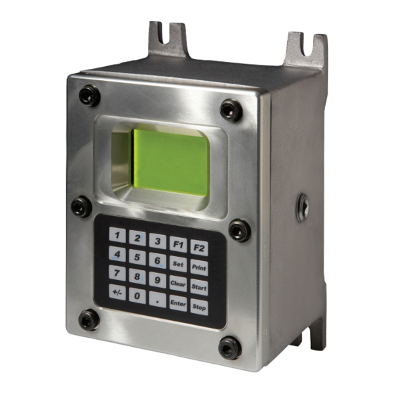
Section II – Display and Controls microFlow.net Gas Display and Controls ™ Figure 1. microFlow.net Gas Display and Controls The user interfaces with the microFlow.net Gas through either through one of its several communications ports or via the display and keypad found on the face of the instrument. The display and keypad alter the format and function based upon the mode (Run Mode, Programming Mode…) that the instrument is currently operating in. -
Page 8: Power Up
Section II – Display and Controls Power Up The following describes the events which occur when the power is applied to a microFlow.net Gas. Upon power up the microFlow.net Gas goes through a start up sequence. The start up screen will be displayed while a RAM test is being performed. - Page 9 Section II – Display and Controls microFlow.net Gas Mass Batch Forward 0 kg Mass Batch Reverse 0 kg < - MORE - > microFlow.net Gas Energy Batch Forward 0 MMBtu Energy Batch Reverse 0 MMBtu < - MORE - > GSV Flow Rate Current Forward Flow Rate 0.0 MSCF/h...
- Page 10 Section II – Display and Controls Batch #XXXX METHANE Batch Start Time XX/XX/XX XX:XX:XX Current Date/Time XX/XX/XX XX:XX:XX < - MORE - > Batch Forward 0.00 MCF 0.00 MSCF MASS 0.00 kg ENERGY 0.00 MMBtu < - MORE - > Batch Reverse 0.00 MCF 0.00 MSCF...
- Page 11 Section II – Display and Controls Current Ref. Density +XXX.X kg/m3 Average Ref. Density +XXX.X kg/m3 < - MORE - > Note: This screen will not be displayed if temperature compensation is not configured. Density (kg/m Cur Ref Dens 0.0000 Cur Obs Dens 0.0000 Average Ref Dens...
-
Page 12: Section Iii - Run Mode
Section III – Run Mode Run Mode The “RUN” Mode is the normal operator-controlled mode of operation where a batch volumes are displayed. All control operations can be performed either locally through the keypad or through communications. The opera- tion described in this section assumes that the microFlow.net Gas is being operated locally through the keypad. For information on operating through communications, refer to the microFlow.net Gas Communications and Reference Manuals. -
Page 13: Section Iv - Program Mode
Section IV – Program Mode Program Mode The microFlow.net Gas has a significant number of customizable features which are selectable by the user. The process of selecting these features and customizing the microFlow.net Gas to each application is performed in the Program Mode. -
Page 14: Entry To Main Directories
Section IV – Program Mode Entry to Main Directories 1. Assert the security input if configured. This will provide the first step for access to program codes. microFlow.net Gas GV Batch Forward 0 MCF GV Batch Reverse 0 MCF < - MORE - > 2. -
Page 15: Changing Program Mode Parameters
Section IV – Program Mode Changing Program Mode Parameters The program codes represent parameters that can be changed either to enhance the performance of the microFlow.net Gas or to accommodate application changes. There are three types of parameters in microFlow.net Gas: codes that require numerical data, codes where an option can be selected from a list, and codes where alphanumeric data is entered. -
Page 16: Section V - Diagnostics
Section V – Diagnostics Main Menu Diagnostics Main Menu Diagnostics allow the operator to review current configurations, identify causes of system errors, and analyze data collected by the microFlow.net Gas. Selecting "Diagnostics" from the main menu, and then choosing a specific diagnostic, usually results in the screen shown directly below. Position the cursor beside the appropriate selection, and then press ENTER to reach the desired diagnostic screen. - Page 17 Section V – Diagnostics If there are active alarms, they will be displayed as follows: Active Alarms - > PA: Power Fail Alarms The active alarms can be cleared from this display by moving the arrow to the alarm and pressing "ENTER." The microFlow.net Gas will then ask for the passcode.
- Page 18 Section V – Diagnostics Press Clear to return to the Diagnostics Menu. Entering the number of batches back, the microFlow.net Gas will display the following screen: - > Batch Totals Boolean/Algebraic From this display, the operator can choose either "Batch Totals" or "Boolean Algebraic." The following information is displayed for Batch Totals.
- Page 19 Section V – Diagnostics Batch #16 Avg Temp 0.00 C Avg Obs Dens 0.0000 kg/m Avg Rel Dens 0.0000 kg/m Press PRINT for help Batch #16 Avg Rel Dens 0.0000 Avg Press 0.00 bar Avg Wobbe Index 0.00 Press PRINT for help Batch #16 Avg Heat Value 0.000...
- Page 20 Section V – Diagnostics Batch #16 Avg Mole % n-Decane 0.0000 Avg Mole % Nitrogen 0.0000 Avg Mole % H2S 0.0000 Press PRINT for help Batch #16 Avg Mole % CO2 0.0000 Avg Mole % Water 0.0000 Avg Mole % Hydrogen 0.0000 Press PRINT for help Batch #16...
- Page 21 Section V – Diagnostics Batch #16 Strt Energy Non Reset (F) 0 MMBtu Strt Mass Non Reset (F) 0 kg IV Non Reset (Fwd) 0 MCF Press PRINT for help Batch #16 GV Non Reset (Fwd) 0 MCF GSV Non Reset (Fwd) 0 MCF Energy Non Reset (Fwd) 0 MMBtu...
- Page 22 Section V – Diagnostics Batch #16 Boolean/Algebraic The first column is the last 5 (#46-50) USERBOOL valves and the second column is the last 5 (#46-50) USERFLOAT valves recorded at the time the batch was reset. Press CLEAR until the "Diagnostics Menu" is displayed. Audit Trail The View Only Diagnostics menu provides the selection "Audit Trail"...
- Page 23 Section V – Diagnostics Digital Outputs The Diagnostics menu provides the selection "Digital Outputs" where the function and status of the digital outputs can be viewed. With the arrow key in front of "Digital Outputs," pressing ENTER will display all six digital outputs and their status.
- Page 24 Section V – Diagnostics This display allows the operator to choose the communication port to be viewed. Pressing the ENTER key when the arrow is in front of the desired communications port will display the data that is being received by the microFlow.net Gas and the response of the microFlow.net Gas.
- Page 25 Section V – Diagnostics User Boolean Registers The User Boolean Registers display indicates the registers and their current True or False value, where 0 is False and 1 is True. User Boolean Regs More... Using the up and down arrows, the 50 User Boolean Registers can be viewed. Pressing CLEAR will return to the Boolean/Algebraic Processing menu.
- Page 26 Section V – Diagnostics Timer Numbers Resolution Range 0.1 second 109 minutes 1.0 second 18.2 hours 1.0 minute 45.5 days 1 hour 7.5 years Clear the timer by writing a zero to the database location of the desired timer. General Purpose Timers Using the up and down arrow keys will display the remaining timers.
-
Page 27: Ultrasonic Diagnostics
850CCEE B Bootloader Rev 00.02 00:50:C2:XX:XX:XX Copyright 2007-2009 FMC Technologies Inc. Pressing CLEAR will return to the Diagnostics menu. Ultrasonic Diagnostics Ultrasonic Data The values shown on these screens are provided by the ultrasonic meter. The microFlow.net Gas collects this infor- mation from the ultrasonic meter via communication on a periodic basis. - Page 28 Section V – Diagnostics Where: Log Count XXXXXXXX - Incremented by the meter each calculation cycle Alarm Status XXXXXXXX - Bit encoded, if zero no alarms present on meter MID Mode Yes/No - European MID mode indicator HW Interlock Locked/Unlocked - Sealing jumper installed DB Checksum XXXXXXXX - Configuration database checksum Press Clear to return to the Ultrasonic Data Diagnostic Menu.
- Page 29 Section V – Diagnostics Provides the signal strength of the paths of the ultrasonic meter. Sig Path Info Signal 1A% 000000 Signal 1B% 000000 Signal 2A% 000000 Signal 2B% 000000 Signal 3A% 000000 Signal 3B% 000000 Press CLEAR to return to the Path Info display. Sig Path Info Signal 4A% 000000...
- Page 30 Section V – Diagnostics Press Clear to return to the Ultrasonic Data Diagnostic Menu. Profile – Indicates current meter profiles Profile Flatness 00000000 Symmetry 00000000 Swirl 00000000 Cross 00000000 Press Clear to return to the Ultrasonic Data Diagnostic Menu. Line Cond. – Indicates current temperature and pressure Line Cond.
-
Page 31: Section Vi - Index
Section VI – Index Active Alarms, 12-13 Alarm History, 12-13 Alphanumeric Data, 11 Audit Trail, 1, 12, 18 Batch Log Stats, 12, 22 Batch Record Log, 12-13 Batch Totals, 14 Boolean/Algebraic, 12, 14, 17-18, 20-22 Communications Monitor, 12, 19 Contrast Adjust, 12, 26 Diagnostics, 12-26 Diagnostics, Ultrasonic, 23 Digital Inputs, 12, 18... - Page 32 Section VI – Index Passcode, 8, 13 Power Fail, 13 Power Up, 8 Product Description, 1 Program Mode, 9-11 Reset Batch, 8, 10 Run Mode, 2-3, 8 Software Version, 12, 22-23 Temperature, 6-8, 26 Transaction, 8, 13 Ultrasonic Diagnostics, 23 Issue/Rev.
-
Page 33: Section Vii - Related Publications
Section VII – Related Publications The following literature can be obtained from FMC Technologies Measurement Solutions Literature Fulfillment at johno@gohrs.com or online at www.fmctechnologies.com/measurementsolutions. When requesting literature from Literature Fulfillment, please reference the appropriate bulletin number and title. microFlow.net Gas Specification ............................ - Page 34 Kongsberg, Norway +47 (32) 28 67 00 San Juan, Puerto Rico +1 (787) 772 8100 United Arab Emirates, Dubai +971 (4) 883 0303 Visit our website at www.fmctechnologies.com/measurementsolutions Printed in U.S.A. © 2/10 FMC Technologies Measurement Solutions, Inc. All rights reserved. MNFG003 Issue/Rev. 0.0 (2/10)
Need help?
Do you have a question about the Smith Meter microFlow.net Gas and is the answer not in the manual?
Questions and answers