Advertisement
If you have any questions about the mounting process do not hesitate to
contact me at info@eowave.com
This kit is not for beginners, you should have soldering skills and
you must know in which direction to put ICs, LEDs & capacitors
Eowave bears no responsibility for mistakes that are made during the
assembly process, or for damage caused to components if they are not
soldered correctly. Read the instructions carefully before starting to
solder. Use the pictures to verify the placement if you have doubts.
Google 'resistor calculator' to work out resistor values from the col,our bands,
or better yet use a multimeter
Glue the caps on the switches (the best method is to use hot glue so you
don't have to wait, otherwise you can use superglue)
Components will take place on 2 sides of the board, the components on one
side, the LEDs and mechanical parts on the other side as follows
Advertisement
Table of Contents

Related Manuals for Eowave DIY 8

Summary of Contents for Eowave DIY 8
- Page 1 This kit is not for beginners, you should have soldering skills and you must know in which direction to put ICs, LEDs & capacitors Eowave bears no responsibility for mistakes that are made during the assembly process, or for damage caused to components if they are not soldered correctly.
- Page 2 Component side mount and solder in the order of the BOM on the following page. Somer additional notes; - all the resistors - ICs (use the socket for the main IC on IC3) do not put the IC (DsPic) into the IC3 socket before you do your first electrical test - smaller capacitors - transistors...
- Page 3 Part List Resistors 220 R34 R1, R2, R5, R6, R10, R11, R14, R15, R16, R17, R21, 18 1k R22, R23, R28, R31, R40, R42, R43 3 5k1 R29, R32, R39 R3, R4, R7, R8, R9, R12, R13, R18, R19, R20, R24, 19 10k R25, R30, R33, R35, R36, R37, R38, R41 2 20k R26, R27 10 Black resistor 1 TL072P/TL082 IC7 2 74HC165N IC1, IC2 2 74HC595N IC5, IC6 1 28 pin socket IC3 1 dsPIC33EV64GM102 Install after test IC3 Caps 2 4n7 Marked 472Z C9, C12 1 10n...
- Page 4 Component side...
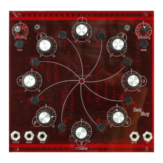
- Page 5 Mechanical part side RED8 RED1 SNAP108 SNAP109 SNAP107 GREEN8 GREEN1 S107 S106 SNAP106 SNAP105 RED7 RED2 GREEN7 GREEN2 LED108 SNAP103 SNAP104 GREEN3 GREEN6 RED3 GREEN5 GREEN4 SNAP101 SNAP102 RESET START RED4 RED5 SNAP100 GATE...
- Page 6 Using the Seq 8 You can find an instructional video on how the modes of the Seq 8 work on the Eowavr youtube channel Inputs : Clock in Reset in Play in (hi level will stop the internal clock sequence) Outputs : CV out switchable between 0-5 V &...
Need help?
Do you have a question about the DIY 8 and is the answer not in the manual?
Questions and answers