Table of Contents
Advertisement
Quick Links
Advertisement
Table of Contents

Summary of Contents for Geotech Solar Sipper
- Page 1 Geotech Sipper Installation and Operation Manual Rev 10/12/2017 Part # 16550176...
-
Page 3: Table Of Contents
Section 7: System Specifications ........................33 Section 8: System Schematics ..........................35 Section 9: Parts and Accessories ........................39 Sipper Pump and Skimmer Parts and Accessories .................... 40 Installation Guide: Desiccant Dryer Kit for Geotech Sipper (Solar or AC) ............41 The Warranty ................................44... - Page 4 DOCUMENTATION CONVENTIONS This manual uses the following conventions to present information: An exclamation point icon indicates a WARNING of a situation or condition that could lead to personal injury or death. You should not proceed until you read and thoroughly understand the WARNING message. WARNING A raised hand icon indicates CAUTION information that relates to a situation or condition that could lead to equipment malfunction or damage.
- Page 5 In order to ensure your Solar Sipper has a long service life and operates properly, adhere to the following cautions and read this manual before use. Controller power input source must not exceed specified ratings. Controller may not operate properly with wiring not supplied by manufacturer.
- Page 6 Notice for consumers in Europe: This symbol indicates that this product is to be collected separately. The following applies only to users in European countries: This product is designated for separate collection at an appropriate collection point. Do not dispose of as household waste. ...
-
Page 7: Section 1: System Description
Electrical power used to run the Solar Sipper is generated on-site by solar panels. The internal compressor is capable of producing up to 20” (51 cm) Hg vacuum and 100 PSI (6.9 bar) pressure. This alternating vacuum/pressure process allows the user to recover a wide range of fluids, from very viscous to ultra- light Non-Aqueous Phase Liquid (NAPL), from depths as deep as 180’... -
Page 8: Recovery Rates
Section 6: System Troubleshooting of this manual. The Solar Sipper Controller is dependent upon the annual average solar resources, which can vary from region to region. Geotech assists in determining how much potential recovery can be expected depending on where the site is and how many solar panels will be required. -
Page 9: Section 2: System Installation
Solar Sipper systems can be modularized and delivered on pallets that can be quickly and easily deployed. This simplifies deployment where existing concrete pads or other infrastructure, does not already exist. - Page 10 on top of poles or other available structures. Other unpredictable factors, such as more or less cloud cover, must be also be considered when planning solar power capacity requirements. Pick a location with a maximum exposure to sunlight. Avoid shadows, especially during the middle of the day.
-
Page 11: Mounting The Control Panel
Mounting the Control Panel The enclosure for the Solar Sipper allows the customer the option to place the control panel in a convenient and accessible location. It is recommended the control panel enclosure be placed out of the direct path of weather and sunlight. If power is to be wired to the enclosure, then all conduit runs are to be rigid metal and grounded to an equipment conductor common for non-current carrying metal parts. -
Page 12: Solar Sipper Wiring
Solar Sipper systems are supplied with 25’ (7.6 m) of 4 conductors 14 AWG cable. DO NOT modify the length of this power cable. After ensuring the power switch on the controller is set to OFF, make all external power connections as shown in Figure 2-3. -
Page 13: Adding Additional Panels
During the winter months when the sunlight decreases, additional solar panels can easily be added to the Solar Sipper system. Additional panels will ensure production during the winter months, when there are fewer hours of sunlight, and the excess energy will not be used in the summer. As a general guideline, up to 4 –... -
Page 14: Grounding
(refer to Figure 8-1 and 8-2.) If the groundwater table level is unknown, Geotech can provide you with an oil/water interface probe to determine the current water level and product layer thickness. Contact Geotech for more... -
Page 15: Product Recovery Tank
This can happen especially where there is low fluid conductivity surrounding the well. It is best to trust the site characterization data and test with a Geotech oil/water interface probe to verify that the float is at the expected level within the well. If you cannot access an oil/water interface probe, or are deploying pumps in a 2”... - Page 16 Figure 2-5: Example of Tankfull Probe...
-
Page 17: Section 3: Timer/Cycle Settings And Display Descriptions
Accessing system status and diagnostic displays. The following pages show examples of all controller displays and a brief description of their function. Contact Geotech Technical Sales for any assistance in operating your Sipper controller. Setup Displays Once the Sipper system has been installed and all wiring to the controller is complete, turn on the main power switch to the Sipper controller. -
Page 18: Start (Runtime) Displays
Press the LEFT arrow button (which will complete the current pump’s cycle time, then return you to the Main Menu). To start the Solar Sipper and activate the runtime to all pumps attached, proceed as follows: From the Main Menu, press the RIGHT arrow button. The following display will appear:... -
Page 19: Stopping Sipper Operation (Runtime)
Low Temp ShutOff The Low Temp Shutoff display (when enabled), will shut down the Sipper controller at 0°C (32°F). Since the Sipper system primarily operates above ground, this feature prevents the controller from operating during a time when product lines could freeze. The Sipper will automatically restart at a temperature of 3.3°C (38°F). -
Page 20: System Status And Diagnostic Displays
These displays contain a variety of information that can be used to record important activity to your Solar Sipper system. These displays can also be viewed during the system’s Runtime by pressing the UP or DOWN arrow buttons at any time during operation. After viewing a status display, leave the system as is. - Page 21 The Solar Sipper controller is designed to shut itself down when the battery voltage reaches 11.4V and will resume operation when the battery charge reaches 12.1V. The Solar Sipper is designed to charge the battery to a maximum of 14.5V.
-
Page 22: Alarm (Condition) And Fault Displays
Sipper controller. Should this display appear, contact Geotech about the fault. Inform the Geotech Technical Sales Representative of all conditions (weather, temperature, vibration, etc.) and when the fault occurred. A fault message of this kind will usually require the unit be sent to Geotech for diagnostics and repair. - Page 23 Figure 3-1: Flowchart of User Interface Label...
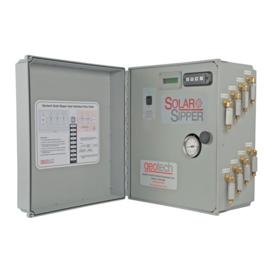
- Page 24 Figure 3-2: Example of Solar Sipper front panel.
-
Page 25: Section 4: System Operation
Section 4: System Operation If Sipper system is to be deployed in humid conditions, it is recommended to install the optional Desiccant Dryer to prevent frequent solenoid maintenance. See Section 9: Parts and Accessories for part information. Establishing the Product Recovery Cycle Time The first thing to consider will be a product recovery rate target. -
Page 26: Initiating The Sipper Runtime
Initiating the Sipper Runtime Once Runtime has been started, the Solar Sipper system will initiate the vacuum cycle for well number one (or whichever well is selected to start), complete that well’s cycle, then continue on through any remaining wells as per the individual user input settings. -
Page 27: Fluid Viscosity
Geotech so that we can determine if more solar panels or batteries are necessary. In some cases, such as in the southwest United States, the standard Solar Sipper can easily outperform the rates shown in the following chart. -
Page 28: Section 5: System Maintenance
Build-up on the controls can result in overheating the electronics and possible failure of components. Verify fluid levels in the well using a Geotech Interface Probe. Make sure the pump and Skimmer are set at the correct interval for collection of product. ... -
Page 29: Yearly Maintenance
Skimmer assemblies. Solar Panel On Solar Sipper applications, it is important to keep all debris, dust and dirt from accumulating on the solar panel surface. Clean the front surface of the solar panel as needed with mild soap and water. DO NOT use abrasive cleaners, solvents or pads. -
Page 30: Solenoid Maintenance (Stuck Solenoid)
Solenoid Maintenance (Stuck Solenoid) The following procedure outlines how to remove, dis-assemble, and clean a stuck solenoid plunger. 1. Remove plug on solenoid with Phillips screwdriver. *Do not lose the gasket for the plug. 2. Remove the three (3) screws and solenoid with a small flathead screwdriver (Figure 5-1). Figure 5-1: Removing Solenoid 3. - Page 31 4. Carefully remove the spring, the O-ring, the bushing, and the plunger (Figure 5-3). Figure 5-3: Solenoid Parts 5. Clean the plunger and plunger cavity with a spray lubricant and cotton swab. *Silicon based or aerosol lubricant OK. 6. Orient and insert the plunger as shown in Figure 5-4. Figure 5-4: Solenoid Plunger 7.
- Page 32 *Be very careful not to lose or allow the gasket to fall out of place and get crushed 11. After securing the solenoid, re-attach the plug with gasket to the solenoid. If this procedure does not resolve a suspected vacuum/pressure problem, then please call Geotech Technical Sales for further troubleshooting advice @ 1-800-833-7953.
-
Page 33: Section 6: System Troubleshooting
System is operating in humid conditions, which can cause residue or debris to accumulate within the solenoid. System may be installed with optional Desiccant Dryers. See Section 9: Parts and Accessories for Desiccant Dryer information, or contact Geotech Technical Sales for assistance. - Page 34 Tankfull probe is disconnected or cable is damaged. Inspect probe and cable. Replace if needed. Verify the tankfull float is not stuck in the UP position. If the tankfull alarm will not clear then contact Geotech for assistance.
- Page 35 Turn unit off and back on to rest the clock crystal. Problem: Counters running slow. Solution: Turn unit off and back on to reset the clock crystal. If your solution cannot be found within this section, please call Geotech Technical Sales for expert troubleshooting advice @ 1-800-833-7958.
-
Page 36: Section 7: System Specifications
Oil/Water Separation Oleophilic/hydrophobic mesh screen Power Power Maximums (AC Sipper) 87 to 240VAC, 2.7 to 1 Amp(s) (Solar Sipper) 12-15VDC input @ up to 14.5 Amps 90 ~240 Watts continuous Power usage will vary depending on application. Controller Operating Temperature 0°... - Page 37 Solar Panel: Rated Power 100 Watts (standard unit) Operating Voltage 17.4 VDC Maximum Voltage 21.5 VDC Operating Amperage 4.88 Amps (standard unit) Maximum Amperage 5.8 Amps Size: 41.2” H x 27.5” W (105 cm H x 70 cm W) Approx. Weight: 23.3 lbs (10.5 kg) Solar Panel Mounting System: Module Tilt Range...
-
Page 38: Section 8: System Schematics
Section 8: System Schematics Figure 8-1: Solar Sipper Schematic... - Page 39 Figure 8-2: AC Sipper Schematic, shown with optional Desiccant Dryers...
- Page 40 Figure 8-3: 8 Well Solar Sipper Internal Wiring Diagram...
- Page 41 Figure 8-4: 3 Well Solar Sipper Internal Wiring Diagram...
-
Page 42: Section 9: Parts And Accessories
MOUNTING RACK,SOLAR PANEL 16550252 CABLE,THW,12AWG SUBMERSIBLE PUMP,BLACK/RED,RIBBON 11200479 BATTERY,SOLAR AGM,104 AH,12V 16550253 Float Switch Assemblies SOLAR SIPPER INTAKE FLOAT SWITCH 86600095 PROBE, TANKFULL, SOLAR SIPPER 25' 56650100 Sipper Well Cap and Tubing Accessories WELL CAP,2",SLIP W/ CMPRSN FTG SIPPER 86600061 WELL CAP,4",SLIP W/ CMPRSN FTG SIPPER... -
Page 43: Sipper Pump And Skimmer Parts And Accessories
Ask your Geotech Sales Representative for more information. Sipper Pump and Skimmer Parts and Accessories See “Geotech Pump and Skimmer Assembly Installation and Operation Manual” (P/N 16550181), for a complete description and listing of available pumps, skimmers, and their accessories. -
Page 44: Installation Guide: Desiccant Dryer Kit For Geotech Sipper (Solar Or Ac)
Installation Guide: Desiccant Dryer Kit for Geotech Sipper (Solar or AC) If operating in humid environments, it is recommended to install a desiccant dryer kit with the Geotech Sipper (Solar or AC) to minimize the amount of moisturized air that enters the pneumatic system. This will minimize solenoid maintenance and optimize compressor performance. - Page 45 Notes...
- Page 46 DOCUMENT REVISIONS EDCF# DESCRIPTION REV/DATE Previous Release 2/15/2013 Added Compressor Repair Kit to Replacement Parts List. 1583 5/24/2013 Added Revision History Table - SP Edited Section 9: Parts and Accessories – Solar Panel now 100 Watts (was 85 Watts), 1713 12/18/2013 updated Solar Panel Specs - SP Edited Section 3: Timer/Cycle Settings and Display Descriptions –...
-
Page 47: The Warranty
Geotech agrees to repair or replace, at Geotech’s option, the portion proving defective, or at our option to refund the purchase price thereof. Geotech will have no warranty obligation if the product is subjected to abnormal operating conditions, accident, abuse, misuse, unauthorized modification, alteration, repair, or replacement of wear parts. - Page 48 Geotech Environmental Equipment, Inc 2650 East 40 Avenue Denver, Colorado 80205 (303) 320-4764 ● (800) 833-7958 ● FAX (303) 322-7242 email: sales@geotechenv.com website: www.geotechenv.com...
Need help?
Do you have a question about the Solar Sipper and is the answer not in the manual?
Questions and answers