
Subscribe to Our Youtube Channel
Related Manuals for Xeos Alert Geomatics Resolute

Summary of Contents for Xeos Alert Geomatics Resolute
- Page 1 Resolute User Manual GNSS RECEIVER - AUTONOMOUS, LOW POWER, TELEMETERED Resolute User Manual Version 2.5 Version 2.5 Aug 2020...
-
Page 2: Contact Us
Email support@alertgeo.com Phone (902) 444-7650 (902) 444-7651 Website www.alertgeo.com About Us: Alert Geomatics is the Geomatics arm of Xeos Technologies Inc., a telemetry, monitoring and tracking company founded in 2004. Version History Version No. Firmware Ver. Date Description 1.1.4147 Nov 2017 RTK Details Added 1.1.4641... -
Page 3: Table Of Contents
Table of Contents Shipped From ........................... i Contact Us ............................i About Us: ............................i Version History ..........................i Overview ............................1 Device Configurations ........................1 Reference ........................... 1 Polar ............................1 RTK PIN Base -RTK Base Receiver ....................1 RTK PIN Rover -RTK Rover Receiver ................... - Page 4 SD Cards Theory of Operation ....................15 Tunnel Theory of Operation ..................... 16 SBD: Theory of Operation ......................18 XBD: Theory of Operation ......................19 Device Configuration........................20 USB Diagnostic Port ........................20 Using STerm and Sending Commands ..................21 Configuration Commands ......................
- Page 5 Confirming GNSS Receiver Operation ..................40 Confirming RTK Radio Operation (Base) .................. 40 Confirming RTK Radio Operation (Rover) ................40 Confirming Cell Operation ......................41 Confirming Cell Operation ......................41 Confirming Iridium Operation ....................41 XeosOnline ............................ 41 Upgrading Firmware ........................41 Appendix A: Command Index .......................
-
Page 6: Overview
Overview The Resolute GNSS Receiver is an autonomous low power GNSS receiver with L1/L2 GPS and GLONASS tracking abilities. Optionally, other satellite constellations and frequencies may be added. The Resolute is powered by a flexible GNSS modem capable of RTK or Standalone data collection. -
Page 7: Northstar
NorthStar The NorthStar is a correction repeater and communications unit that has two primary functionalities relating to RTK receivers. First, it can be a correction relay unit to overcome geographical issues such as distance and topography between the RTK Base and RTK Rover. Secondly, can also be utilized as a collection point for RTK Rover data. -
Page 8: Device Preparation
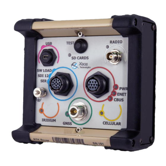
Device Preparation Making the Connection No. Name Function USB-Mini Provides access for configuration of device for deployment via PC Test Button Used as a test to check if the device is working properly and should turn all the LEDs on. It also initiates the device’s connection to its peripheral devices. - Page 9 The Type N connector on the panel is supplied to attach to one of the many supported GNSS antennae. Depending on what modems (iridium, cellular or radio) you have installed, there may also be TNC connectors for the various telemetry options as indicated on the label. The 10-pin circular Souriau connector contains the power connections.
-
Page 10: Removable Door: Sd Cards Access And Sim Installation
Removable Door: SD cards Access and SIM Installation The Resolute has a removable door that allows access to the SD cards that are shipped with your Resolute along with access to the SIM slots for optional Cell and Iridium Telemetry. Using a 3/32 Allen key, the four captive fasteners pictured below can be unscrewed from the main housing. -
Page 11: Retrieving Sd Cards
Retrieving SD Cards The two SD cards are of the microSD form factor and are mounted on a single removable cartridge on the left side of the Resolute box. To remove the SD cartridge, grasp the edges and pull in the direction of the opening of the enclosure. When replacing the SD cartridge, note that the orientation of the cartridge does not matter as long as the cartridge is fully seated in its slot. -
Page 12: Installing The Iridium Sim
If your unit comes equipped with an Iridium modem, it requires a SIM to operate. Iridium SIMs can be purchased through the parent company, Xeos Technologies, an Iridium Value Added Reseller. If only using SBDs, a register only SIM is required. If using RUDICS, your SIM will need to be activated for RUDICS use. -
Page 13: Installing Power To The Unit
Cell SIM Inserted on Cell modem (4) Installing Power to the Unit The Resolute requires power supply capable of sourcing three amp surge currents at 12 V. this can be reduced to one amp if no Iridium or Cellular modem is present. The power cable supplied has a red ring that matches the red ring of the power connector on the box. -
Page 14: Test Button And Led Behavior
Test Button and LED Behavior Test Button Operation The test button operation is controlled by variable length button presses. Additional confirmation feedback to these button presses is provided by the response of the LEDs. A summary table is provided at the bottom of this subsection. To turn on the lights, press the test button (roughly one second press). - Page 15 Power LED Behaviour Meaning Reverse voltage applied Green Unit is powered No LED Unit is not powered SD LED Behaviour Meaning SD Cards unmounted / Safe to remove Yellow 1 SD card mounted. Not safe to remove Flashing Yellow 1 SD card mounted, and writing to card. Not safe to remove Green 2 SD cards mounting.
-
Page 16: Installing A Resolute
Installing a Resolute When installing a Resolute it is important to choose the installation site thoughtfully. It should be noted that there are differences when installing Rovers, Bases, and Reference receivers which will be highlighted in the following sub sections. RTK Radio Network Design Before leaving the office, if your unit includes a radio for broadcasting or receiving corrections, best practice is to determine the radio network for your device. -
Page 17: Installing The Radio Antenna
A-03-058 GNSS Antenna Mount Appendix C for specific GNSS antenna mount installation instructions if you purchased an antenna and mount from Alert Geomatics. Installing the Radio Antenna If your unit is equipped and configured to send information over radio, installing a radio antenna is necessary. -
Page 18: Installing The Cell Antenna
of the antenna is the “front” of the antenna when orientating. The antenna comes equipped with mounting hardware. Bases can be equipped with Yagi or Omni antennas depending if they are broadcasting to a single endpoint, or multiple end points. If multiple end points for the corrections from the base are needed, an Omni antenna must be used. - Page 19 will allow the RTK Rovers attached to the Base to make relative measurements from this position. The unit will store this information through power resets. Resolute User Manual Version 2.5...
-
Page 20: Device Theory Of Operation
Device Theory of Operation The Resolute at its heart is an embedded peripheral control unit. All enabled peripherals, including the GNSS are controlled by a scheduler, which can be controlled by the user. Each peripheral has three separate timer settings using the scheduler: duration, interval and offset. Duration is the length of time the peripheral is on. -
Page 21: Tunnel Theory Of Operation
If your unit is equipped with a Cellular modem or Iridium modem and a data or RUDICS plan, your unit is capable of remotely connecting to the Xeos Tunnel. The Tunnel is useful for configuring your unit remotely and retrieving data and diagnostics from the SD card remotely. It is also useful for diagnosing potential issues on units deployed in the field. - Page 22 Iridium Tunnel and SBD Network Diagram Upon reaching its start time, the tunnel will power on the configured modem and will attempt to open a two way connection to XeosOnline (XO). The tunnel confirms two way operation to XO via a heartbeat message known as a “keep alive”. A keep alive is a small data packet sent from the unit to the XO server every 15 seconds and acknowledged by the server.
-
Page 23: Sbd: Theory Of Operation
Iridium Keep Alives in the XeosOnline Message Tab Tunnel connections over cellular are normally stable (in good cellular coverage). Tunnel connections over Iridium RUDICS will have interruptions under normal operation. The maximum data transfer rate of Iridium RUDICS is 17 KB/min. The user of the remote device can interact with the device through a number of interface (sockets) into the tunnel. -
Page 24: Xbd: Theory Of Operation
Any messages sent by the user between then last message check and the next message check will wait on the Xeos Online server for the unit to check in. The unit requires an unlock code in order for any message sent to the unit to issue a command to prevent undesired command and control. -
Page 25: Device Configuration
Device Configuration All of the settings on the Resolute can be configured either by connecting one of the diagnostic ports to a serial port terminal, the USB port, or by sending configuration commands from a remote location over the Iridium Satellite Network or Cellular SMS (telemetry options needed). If configuring the unit locally, USB is recommended. -
Page 26: Using Sterm And Sending Commands
Data Bits Parity None Stop Bits Flow Control Disabled Using STerm and Sending Commands An STerm Window STerm is the officially supported serial port terminal program of Alert Geomatics. Sterm can load configuration files to allow the commands for Alert Geomatics products to appear as buttons on the right side of the window. -
Page 27: Configuration Commands
STerm Serial Port Settings Menu The buttons on the right side of the window can be edited to change the input variable you are sending to the device. This is done by hovering over the right side of the button and then clicking the green edit button. -
Page 28: Gnss Configuration
peripheral is on. Interval is the how often the device comes on. Offset offsets the interval by the specified amount of time. Peripherals can be enabled or disabled using “$(function)SetEnabled T/F”. For example, the following setting will enable the GNSS module: $GnssSetEnabled T When adjusting the timing settings, the time input can take form of seconds (by default, if no units are entered), minutes, hours or days. - Page 29 GNSS’s duration parameter specifies the length of time the GNSS peripheral is on. This timer can range from 30 seconds to always on (infinite). To change this timer, issue the following command: $GnssSetDuration [time] The variable time is length of the timer. For example, to turn on a unit for a duration of 3 hours, you would enter the following command: $GnssSetDuration 3h GNSS’s interval timer is the length of time between the on periods of the GNSS (start of one...
- Page 30 Alternatively, command line messages can be sent to configure unit signals and messages enabled. For Iridium SBD, these are best formed on XeosOnline using the ‘admin’ option (user must be an admin level user to see the button on the top bar). To configure and send the command to a unit, click on the two-directional arrow button under the Admin page next to the particular unit to open the Resolute Configuration window.
- Page 31 1 for 2 hours with an update interval of 1 second. Conversion of the chosen File Duration, Update Interval and Message Blocks from the drop-down menus to their respective codes is done internally by Xeos Online. Resolute User Manual Version 2.5...
-
Page 32: Collecting Rinex Data
Collecting RINEX Data The Resolute does not naturally record in RINEX (Receiver Independent Exchange) format, but native SBF files can be converted to RINEX. To log the SBF equivalent of RINEX observation files, enable the “MeasEpoch” SBF message in stream 1 or 2. To log the equivalent of the Navigation RINEX files, log the GPSNav or GloNav, or respective Nav SBF block for the satellite constellations enabled in stream 3 or 4 of the Resolute. -
Page 33: Recording External Sensors
Serial 2 port, as well as streamed over a cellular tunnel connection to a port on Xeos Online (Beta Feature). To configure the output of the RTCM corrections a bitmap parameter must be set. The command for this is $rtcmsetoutputbitmap [value]. -
Page 34: Sd Memory Management
Recording Binary Data The Resolute can record binary data from other sensors. Contact Alert Geomatics for more details. SD Memory Management The data produced by the Resolute is written to two microSD cards. As the data generated by the Resolute fills the card, files will automatically be deleted by a memory management task. The task measures the size of the files on the SD cards. - Page 35 be set higher than the disconnect voltage of the LVD. The restart voltage must be set with the “setrestartvoltage [voltage]” command. This should be set a few hundred millivolts above the shutdown voltage. The default restart voltage is 11.7 V. The three commands required to configure the shutdown voltage are shown for a shutdown voltage of 10.5 V and a restart voltage of 10.8V.
-
Page 36: Rtk Radio Network Design
RTK Radio Network Design The Resolute RTK units contain an embedded radio peripheral for sending and receiving RTK corrections. The radio peripheral included with RTK and NorthStar units operate on a channel basis, with 8 possible channels (0-7). For a simple single-Base-single-Rover network, all the radios should operate on the same channel to receive the corrections. - Page 37 In the configuration where a base is only broadcasting to a single NorthStar, the Base would need to be equipped with a Yagi antenna pointed at the NorthStar. NorthStar Radio A would be equipped with a Yagi Antenna pointed at the Base, while NorthStar Radio B would be equipped with an Omni Antenna to broadcast to multiple Rovers.
-
Page 38: Radio Configuration
Avoid overlapping base coverage boundaries. Radio Configuration The radios as configured from the factory will work for a single Base, multiple Rover RTK network. If a NorthStar Repeater was included in your order, the Rovers will be configured to receive from a single NorthStar. -
Page 39: Embedded Telemetry Data Transfer: Ip Tunnel Configuration
The tunnel grants access to the embedded servers on the device and manages the connection to the Xeos Online server. Tunnel timers are useful if you have either a Cellular or Iridium modem. The Resolute needs to be configured with which modem should be prioritized for connections to the tunnel. -
Page 40: Ethernet Configuration
SBD, XBD and SMS can be configured individually using the interval and offset timer commands. SBD and XBD duration timer is 3 minutes and is NOT configurable . The commands to configure the timers are below and operate on the same principals outlined in detail in the GNSS section: $SmsSetInterval [time] $SmsSetOffset [time] $SbdSetInterval [time]... -
Page 41: Ethernet Latency Configuration
$ethernetSetNetMask Sets the configured ethernet netmask ethernetSetNetMask 255 111 111 111 111 (space delimited) 255 255 0 $ethernetGetMac Returns the set mac address of the ethernetGetMac Resolute (default: aa bb cc dd aa bb) $ethernetSetMac aa Sets the mac address ethernetSetMac F1 3A 83 bb cc dd ee ff gg 3C 6F BF... -
Page 42: Accessing The Http Server
Scripts that are used for downloading data use the HTTP socket and must be disabled by Alert Geomatics to allow other use of the HTTP socket. Contact Alert Geomatics for more information about connecting to the embedded servers over the tunnel, your IP must be cleared to access your device. Accessing the HTTP Server Over Ethernet, the HTTP server can be accessed on port 80 by typing the set IP into a connected computer using any standard web browser. -
Page 43: Automatic File Retrieval (Auto-Downloader)
If you wish to retrieve files from the embedded HTTP server on a consistent basis it is possible to run a script to download all new files on the unit either through the Tunnel to the Xeos Server or over the local Ethernet connection to the device operating the script. The script will automatically start downloading files for the duration of the connection. -
Page 44: Xeosonline Status Of Health
command that responds in a multiline list will not reply. Both Outgoing and incoming messages can be viewed in the messages tab on XeosOnline. XeosOnline Send Message Window XeosOnline Status of Health If a Cell or an Iridium modem is connected to XeosOnline, the Resolute will naturally output status of health (SOH) messages. -
Page 45: Confirming Device Operation
Confirming Device Operation Confirm Power to the Unit After plugging in the power connector, the unit will flash all of its LEDs. Confirm the power LED is green. If red, reverse the voltage supplied to the unit. Confirming SD Cards Mounted Shortly after start up the processor, will try to mount the SD cards, and the LED should change from Red to Green. -
Page 46: Confirming Cell Operation
After the start time pass the unit will attempt to connect to Xeos Online. If the connection is successful, the Cell LED will turn solid green. Note: Testing SMS only confirms the SMS portion of the connection. The data portion of the connection if being used should be tested either with XBD or the tunnel. - Page 47 Send the following commands to turn off GNSS and Radio respectively: $gnsssetenabled f $radiosetenabled f On the top menu bar, navigate to Send File and click on Send Bootload Image. The Firmware Image Send window will open and you will need to select the new version of firmware by clicking the …...
- Page 48 $ver If the new version wasn’t properly uploaded resend the image. To view all the firmware images on the Resolute, use the $imglst command. Delete the old firmware using $imgdelete command. In this example, firmware version 4275 was uploaded so 4262 must be the old firmware. Enter $imgdelete followed by the version number omitting the zeroes and replacing periods with a space.
-
Page 49: Appendix A: Command Index
Appendix A: Command Index Command Variables Description Sample $resetnow Resets the unit $resetnow $schedule Returns schedule of all $schedule enabled peripherals $ver Returns the firmware $ver version loaded $getserialnumber Returns the device serial $getserialnumber nubmer $GnssSet5vAnt T (true) sets the antenna $GnssSet5vAnt T voltage to 5V, F(false) the default, sets the antenna... - Page 50 the tunnel $tunnelgetenabled Returns the enabled state $tunnelgetenabled of the tunnel $tunnelsetmodem [0-3],[2-3] Sets the priority of $tunnelsetmodem 0 3 multiple cell and iridium modems $tunnelsetduration s,m,h,d Set the duration of the $tunnelsetduration 600s tunnel connection $tunnelgetduration Returns the duration of $tunnelgetduration the tunnel connection $tunnelsetinterval...
- Page 51 Appendix reference point, also used for RINEX header $gnssgetantennatype Returns the set antenna $gnssgetantennatype Set the antenna offset for gnssSetAntennaOffsets 0 0 0 gnssSetAntennaOffsets characters RINEX header [E-Offset] [N-Offset] [U-offset] $gnssGetAntennaOffse Get the antenna offset $gnssGetAntennaOffsets for RINEX header $gnssSetAntennaSerial Set the antenna offset for $gnssSetAntennaSerialnumber number...
- Page 52 $gnssGetObserverCom Get the obersever $gnssGetObserverComment ment comment for RINEX header $gnssSetMessageType [stream] GNSS message $gnssSetMessageTypes 1 0 2 1 [duration] configuration bitmaps [update interval] [Bitmap A] [Bitmap B] $gnssgetMessageType Returns enabled message $gnssgetMessageTypes types bitmap $gnssSetSignalTracking [signals GNSS signal tracking $gnssSetSignalTracking 1f (HEX)] configuration bitmaps...
- Page 53 $AESSetDuration [Duration] Set ASCII External Sensor $AESSetDuration 1m Logging timeout duration $AESGetDuration Get ASCII External Sensor $AESGetDuration Logging timeout duration $AESSetInterval [Interval] Set ASCII External Sensor $AESSetInterval 1h Logging interval $AESGetInterval Get ASCII External Sensor $AESGetInterval Logging interval $AESSetOffset [Offset] Set ASCII External Sensor $AESSetOffset 15m Logging Offset...
-
Page 54: Appendix B: Antenna Type Index
Appendix B: Antenna Type Index 0: TWI3870+GP 49: AERAT2775_41 98: ASH700936E_C 1: SEPPOLANT_X_MF 50: AERAT2775_42 99: ASH700936E_C SNOW 2: 3S-02-TSADM 51: AERAT2775_42+CR 100: ASH700936F_C 3: 3S-02-TSATE 52: AERAT2775_43 101: ASH701008.01B 4: ACC123CGNSSA_XN 53: AERAT2775_43 SPKE 102: ASH701023.A 5: ACC2G1215A_XT_1 54: AERAT2775_443 103: ASH701073.1 6: ACC3G1215A_XT_1 55: AERAT2775_443 SPKE... - Page 55 147: ASH701975.01BGP 200: JAVGISMORE 253: LEIAR25.R3 148: ASH802129 201: JAVGRANT_G3 254: LEIAR25.R3 SCIS 149: ASH802147_A 202: JAVGRANT_G3+GP JVGR 255: LEIAR25.R3 SCIT 150: ASH_LOCUS 203: JAVGRANT_G3+GP 256: LEIAR25.R4 LEIT 151: AYIHY-BGLRB06RT 204: JAVGRANT_G3TJ 257: LEIAR25.R4 152: CHANV3 205: JAVGRANT_G3TJ+G JVGR 258: LEIAR25.R4 SCIS 153: CHATK2 206: JAVGRANT_G3TJ+G...
- Page 56 306: MPLL1/L2_SURV 359: SEPPOLANT_X_MF 412: THANAP002 307: MPL_WAAS_2224NW 360: SEPPOLANT_X_SF 413: TIAPENG2100B 308: MPL_WAAS_2225NW 361: SEP_POLANT+ 414: TIAPENG2100R 309: NAVAN2004T 362: SEP_POLANT+_GG 415: TIAPENG3100R1 310: NAVAN2008T 363: SLGSL600_V1 416: TIAPENG3100R2 311: NAVANT3001A 364: SMICR3B 417: TIASMT888-3GV3 312: NAVANT3001B 365: SMICR3B SPKE 418: TOP700779A 313: NAVRT3010S...
- Page 57 465: TPSPG_S1 491: TRM33429.00-GP 517: TRM59800.80 SCIS 466: TPSPG_S1+GP 492: TRM33429.20+GP 518: TRM59800.80 SCIT 467: TPSPN.A5 493: TRM33429.20+GP TCWD 519: TRM59900.00 468: TPSPN.A5 SCIS 494: TRM33429.20+GP UNAV 520: TRM59900.00 SCIS 469: TPSPN.A5 SCIT 495: TRM36569.00+GP 521: TRM65212.00 470: TPSPN.A5 TPSH 496: TRM39105.00 522: TRM77970.00 471: TPS_CR.3...
-
Page 58: Appendix C: Gnss Antenna Mount Diagram
Appendix C: GNSS Antenna Mount Diagram Talisman Mount Diagram A-03-058 Resolute User Manual 1.4... -
Page 59: Appendix D: Rf Cable Installation Diagrams
Appendix D: RF Cable Installation Diagrams Resolute User Manual 1.4... -
Page 60: Appendix E: Example Rtk Network Map
Appendix E: Example RTK Network Map Resolute User Manual 1.4... -
Page 61: Appendix F: Mechanical Specifications
Appendix F: Mechanical Specifications Resolute User Manual 1.4... -
Page 62: Appendix G: Power Requirements
Appendix G: Power Requirements The following section specifies power requirements for various configurations of the resolute with various use cases of duty cycling peripherals. Measurements can fluctuate as receivers and modems use varying power depending on the rate of transmitting, tracking settings and other factors. -
Page 63: Appendix H: Rxtools Download
Appendix H: RxTools Download Download the RxTools software and manual from https://manuals.alertgeo.com/RxTools/ RX Tools contains the SBF Converter to convert SBF blocks to ASCII or RINEX. SBF Block info can be found in the SBF Reference Guide also in the link above. Resolute User Manual 1.4... -
Page 64: Appendix I: Iridium Service
XeosOnline presents the information in a “readable” format and displays it on street level maps. If you wish to use a RUDICS tunnel, please contact Xeos for assistance in setting up and managing a RUDICS tunnel if you do not already have one established. -
Page 65: Warranty, Support And Limited Liability
Xeos Technologies Inc. Limited Warranty and that is returned to Xeos Technologies Inc. with a copy of your receipt. This Limited Warranty is void if failure of the product has resulted from accident, abuse, or misapplication. Any replacement product will be warranted for the remainder of the original warranty period or ninety (90) days, whichever is longer.
Need help?
Do you have a question about the Alert Geomatics Resolute and is the answer not in the manual?
Questions and answers