Subscribe to Our Youtube Channel
Summary of Contents for ATV NLPW229
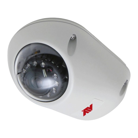
- Page 1 QUICK GUIDE MINI DOME NETWORK CAMERA Please read this manual thoroughly before use and keep it handy for future reference.
- Page 2 2...
-
Page 3: Explanation Of Graphical Symbols
WARNING TO REDUCE THE RISK OF FIRE OR ELECTRIC SHOCK, DO NOT EXPOSE THIS PRODUCT TO RAIN OR MOISTURE. DO NOT INSERT ANY METALLIC OBJECTS THROUGH THE VENTILATION GRILLS OR OTHER OPENINGS ON THE EQUIPMENT. CAUTION CAUTION RISK OF ELECTRIC SHOCK DO NOT OPEN CAUTION: TO REDUCE THE RISK OF ELECTRIC SHOCK, DO NOT REMOVE COVER (OR BACK) -
Page 4: Fcc Compliance Statement
FCC COMPLIANCE STATEMENT This device complies with Part 15 of the FCC Rules. Operation is subject to the following two conditions: (1) this device may not cause harmful interference, and (2) this device must accept any interference received, including interference that may cause undesired operation. FCC INFORMATION: This equipment has been tested and found to comply with the limits for a Class A digital device, pursuant to Part 15 of the FCC Rules. - Page 5 IMPORTANT SAFETY INSTRUCTIONS Read these instructions. Keep these instructions. Heed all warnings. Follow all instructions. Do not use this apparatus near water. Clean only with dry cloth. Do not block any ventilation openings. Install in accordance with the manufacturer’s instructions. Do not install near any heat sources such as radiators, heat registers, stoves, or other apparatus (including amplifiers) that produce heat.
- Page 6 1 Introduction The network camera supports the network service for a sensor image with progressive scan, which can be monitored on a real-time screen regardless of distances and locations. By using its dedicated program, many users are able to have an access to the network camera at once or a single user can monitor various network cameras at the same time.
-
Page 7: Installation
2 Installation 2.1 Installation Rubber Washers (Waterproof) Desiccant Pack 7... -
Page 8: Basic Configuration Of Camera System
2.2 Basic Configuration of Camera System Connection Connector Description Ethernet, RJ-45 port compatible with RJ-45 10/100Mbps having PoE Modular Jack DC Jack Main Power, DC Jack, DC 12V The camera must be installed by qualified service personnel in accordance with all local and federal electrical and building codes. -
Page 9: Micro-Sd Card Insertion
2.3 Micro-SD Card Insertion User can install and change Micro-SD card as shown in the following picture. 2.4 Connections • Connecting the Network Connect a standard RJ-45 cable to the network port of the camera. Generally a crossover cable is used for directly connection to PC, while a direct cable is used for connection to a hub. -
Page 10: Network Connection & Ip Assignment
2.5. Network Connection & IP assignment The camera supports the operation through the network. When a camera is first connected to the network, it is necessary to allocate an IP address to the device with the SmartManager utility on the CD. (Default IP 192.168.30.220) 1) Connect the network camera/device to the network and power up. -
Page 11: Operation
3 Operation The network camera can be used with Windows operating system and browsers. The recommended browsers are Internet Explorer, Safari, Firefox, Opera and Google Chrome with Windows. NOTE: To view streaming video in Microsoft Internet Explorer, set your browser to allow ActiveX controls. -
Page 12: Access From The Internet
3.2 Access from the internet Once connected, the network camera is accessible on your local network (LAN). To access the network camera from the Internet you must configure your broadband router to allow incoming data traffic to the network camera. To do this, enable the NAT traversal feature, which will attempt to automatically configure the router to allow access to the network camera. -
Page 13: Live View Page
3.4 Live View Page The Live View page comes in several screen modes: 1920x1080, 1280x1024, 1280x720(960), 1024x768, 704x480(576), 640x480(360) and 320x240. Users are allowed to select the most suitable one out of those modes. Adjust the mode in accordance with your PC specifications and monitoring purposes. - Page 14 2) Control toolbar The live viewer toolbar is available in the web browser page only. It displays the following buttons: The Stop button stops the video stream being played. Pressing the key again toggles the play and stop. The Play button connects to the network camera or starts playing a video stream. The Pause button pauses the video stream being played.
- Page 15 3.5 Playback The Playback window contains a list of recordings made to the memory card. It shows each recording’s start time, length, the event type used to start the recording, calendar and time slice bar indicates if the recording is existed or not. The description of playback window follows.
- Page 16 3) Time Chart Display an hour-based search screen for the chosen date. If there is recording data, a blue section will be displayed on a 24-hour basis. If you select a particular hour in the chart, a yellow square on the hour will be displayed. 4) Speaker Control Bar Use this scale to control the volume of the speakers.
-
Page 17: Network Camera Setup
3.6 Network Camera Setup This section describes how to configure the network camera. Administrator has unrestricted access to all the Setup tools, whereas Operators have access to the settings of Basic Configuration, which are Live View, Video & Image, Audio, Event, Dome Configuration, and System. -
Page 18: System Requirement For Web Browser
• Using the Reset button: Follow the instructions below to reset the network camera to the factory default settings using the Reset button. 1. Switch off the network camera by disconnecting the power adapter. 2. Press and hold the Reset button on the board with your finger while reconnecting the power. 3. - Page 19 19...
- Page 20 MINI DOME NETWORK CAMERA 5030xxxxA 20...


Need help?
Do you have a question about the NLPW229 and is the answer not in the manual?
Questions and answers