
Summary of Contents for SNK-S ZH701-S5
- Page 1 Integrated High Speed Dome Camera Installation Guide Indoor Version 3.7 00P6H7010ZXSEC7...
- Page 2 Installation Guide Preface The information given in this manual was current when published. The company reserves the right to revise and improve its products. All specifications are subject to change without notice. Notice This manual provides the installation information for the indoor integrated high speed dome.
- Page 3 Installation Guide This symbol on the product or on its packaging indicates that this product shall not be treated as household waste in accordance with Directive 2002/96/EC. Instead it shall be handed over to the applicable collection point for the recycling of electrical and electronic equipment.
- Page 4 Installation Guide Warnings and Cautions • Handle the camera carefully Do not abuse the camera. Avoid striking, shaking, etc. The camera could be damaged by improper handing or storage. • Installing electricity wiring carefully Ask qualified personnel of electrical wiring for the installation. Please note that input electricity to the unit is at tolerance of DC 12V/AC 24V ±...
- Page 5 Installation Guide • Never face the camera towards the sun Do not aim the camera at bright objects. Whether the camera is in use or not, never aim it at the sun or other extremely bright objects. Otherwise, the camera may be smeared or damaged.
-
Page 6: Table Of Contents
Installation Guide Table of Contents Introduction........................7 Standard Package Contents ..................8 Camera Setups and Cable Connections ..............10 Dome Camera Setups....................10 3.1.1 Switch/Connector Definition................. 10 3.1.2 Communication Switch Setting ..............12 3.1.3 ID Setting ..................... 13 3.1.4 Camera Control Protocol Setting ..............13 Cables and Connections .................... - Page 7 Installation Guide System Expansion ....................57 Connecting with Connector Box ................. 57 Data Formats Transforming ..................58 Signal Distribution Unit ....................59 System Integration ....................60 Using Pelco Keyboard....................60 Using Philips Allegiant Keyboard ................61...
-
Page 8: Introduction
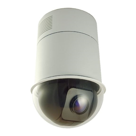
Installation Guide Introduction The Integrated High Speed Dome Camera is designed to deliver superb performance and durability with an intelligent and stylish housing that is suitable in any security and surveillance installation. In addition, the Dome Camera supports one cabling for easy installation. Large set of built-in protocols, including DSCP, Pelco, VCL, Philips, AD-422 (Manchester), etc., provide connectivity to other suppliers’... -
Page 9: Standard Package Contents
Installation Guide Standard Package Contents Before proceeding, please check the box contains the items listed here. If any item is missing or has defects, DO NOT install or operate the product and contact your dealer for assistance. Analog Model Data Cable for Power Supply, Video and RS-485 (DC 12V) Camera Body Data Cable for Power Supply, Video and RS-485... - Page 10 Installation Guide Network Model Data Cable for Power Supply, Video and Audio (DC 12V) Data Cable for Power Supply, Video and Audio Camera Body (AC 24V) Hard Ceiling Mount and M3 Screw, Fixing Plate Optical Cover Decoration Ring Power Adaptor & Power Quick Guide CD: Operation Manuals Cord (DC model only)
-
Page 11: Camera Setups And Cable Connections
Installation Guide Camera Setups and Cable Connections Before installing or connecting the Dome Camera, please refer to this section and complete preparations for dome setups and various switch settings. There will be a PE cloth sheet covered inside the dome cover and a lens cap on the lens for shipping protection. - Page 12 Installation Guide Analog Model Network Model Camera Control Protocol Switch None Communication Switch Communication Switch (Reserved) None RJ-45 Connector 22-Pin Connector 22-Pin Connector ID Switch None Reserved Reboot Button ISP Connector (for FW upgrade) Factory Reset Button ISP Connector (for FW upgrade) NOTE: DO NOT change the network Speed Dome Camera’s Communication Switch factory default settings.
-
Page 13: Communication Switch Setting
Installation Guide 3.1.2 Communication Switch Setting Communication Switch SW 1 RS-485 Setting SW 2 SW 3 Termination Line Lock SW 4 Factory Default Reset SW 5 Reserved SW 6 RS-485 is the interface that communicates the Dome Camera and its control device;... -
Page 14: Id Setting
Installation Guide 3.1.3 ID Setting Please change the analog Dome Camera’s ID if there is more than one Dome Camera on the same installation site. Use the switch to change your speed Dome Camera’s ID by turning the arrow to the desired number respectively. For instance, if the camera’s ID is 123, the ID switch should be set as below. - Page 15 Installation Guide Switch No. Protocol Baud Rate 9600 Pelco D 2400 Pelco P 4800 Chiper 9600 Philips 9600 DSCP 9600 AD422 4800 DM P 9600 Pelco D 4800 Pelco D 9600 Pelco P 2400 Pelco P 9600 9600 Kalatel-485 9600 Kalatel-422 4800 Select protocol: Pelco D, with switch no.
-
Page 16: Cables And Connections
Installation Guide Cables and Connections The Dome Camera is supplied with one integrated 22-pin Data Cable for connecting with the power, video, and RS-485/audio input & audio output cables. Please read the following sections thoroughly before making connections. 3.2.1 Cable Requirements For operation, the Integrated High Speed Dome Cameras require video, RS-485 and power cables as described below: •... -
Page 17: Network Model
Installation Guide AC 24V Data Cable NOTE: Be careful not to pull the cables improperly during installation. Additionally, it is suggested to fasten the cables after cable connection is completed. Furthermore, when wiring the AC 24V power cable, make sure the Ground wire inserted into the mid-pin of the terminal block. -
Page 18: 22-Pin Connector Definition
Installation Guide 3.2.3 22-Pin Connector Definition With the 22-pin connector, installers can simply connect the power, video and RS-485 cables to the Dome Camera at once. Particularly, the alarm pins are serviceable for connecting alarm input and output devices, such as alarm sensors, sirens or flashing lights with the surveillance system. -
Page 19: Network Model
Installation Guide Network Model The network Speed Dome Camera’s 22-pin connector definition is listed below: Definition Cable Definition Cable AC 24-1/DC (+) 20AWG/18AWG ALM-1 ALM NC ALM-3 AC 24-2/DC (-) 20AWG/18AWG ALM-2 ALM NO ALM-4 20AWG/18AWG Reserved ALM COM Reserved Audio in Reserved Audio out... -
Page 20: Cable Wiring And Connection
Installation Guide 3.2.5 Cable Wiring and Connection Users may need to conduct cable wiring when: (1) Connecting self-provided cords to the connector housing (shown in the figure below) instead of using the equipped data cable or (2) Connecting alarm input and output devices. The table follows will illustrate the way to wire cords into the connector housing (shown in the figures below). -
Page 21: Ethernet Cable Connection
Installation Guide Connect the 22-pin connector to the Dome Camera. 3.2.6 Ethernet Cable Connection Connect one end of the CAT5 Ethernet cable to the RJ-45 connector of the network Speed Dome Camera, and the other end of the cable to the network switch or PC. -
Page 22: Dome Camera Installation
Installation Guide Dome Camera Installation Basing on user’s installation environments, the Dome Camera can be installed on ceiling, on wall or on pole. In the following sections, various indoor Dome Camera installation accessories, installation methods and installation procedures will be described in detail. In addition, the next section will provide the Dome Camera’s dimensions for your reference before installation. -
Page 23: Optional Accessories
Installation Guide Optional Accessories Dome Camera Accessories Transparent/Vandal Proof/Smoke Cover Transparent Cover (Standard) Smoke Cover Vandal Proof Cover (Optional) Power Adapter 77H07-A1015 (Input: 100~115VAC/Output: 24VAC 36VA) 77H07-A2015 (Input: 220~230VAC/Output: 24VAC 36VA) NOTE: When wiring, make sure the G/Y wire (Ground) inserted into the mid-pin of the terminal block. - Page 24 Installation Guide T-Bar Ceiling Mount For in-ceiling Installation use. Height: 160 mm (6.3 inches); Diameter: 180 mm (7.1 inches); 0.5 kg (1.1 lbs) Ceiling Panel For ceiling mounting. Zn platted; 610×305 mm (24×12 inches); Diameter: 155 mm (6.1 inches) Standard Pendent Mount White;...
- Page 25 Installation Guide Compact Pendent Mount 184×104×115.2 mm (7.24×4.09×4.54 inches); 0.6 kg (1.2 lbs) Supplied with rubber washer-8 x1, pendent tube washer x1, spring washer-8 x1 and M8x12 screw x1. Straight Tube Iron; Height: 250/500 mm (9.8/19.7 inches); Diameter: 50 mm (2 inches) 1 kg (2.2 lbs) / 1.8 kg (4 lbs).
- Page 26 Installation Guide Indoor Mount Kit For mounting indoor Dome Camera onto a pendent mount/Straight Tube/ Swan Tube. Diameter: 140 mm (5.5 inches); Height: 74 mm (2.9 inches); 0.3 kg (0.7 lbs) Attached Components: Waterproof Rubber, Hexagon Key, Lock Screw Plate, M5x8 screw×1, M5x8 security screw×1, M3x6 screw×1 Corner Plate Mini For mounting with Compact Pendent Mount.
- Page 27 Installation Guide Pole Thin Direct Mounting 232(L)×136(W)×60(D) mm (9.1×5.4×2.4 inches); Diameter: 112~130 mm (4.4~5 inches); 0.7 kg (1.6 lbs). Supplied with stainless steel straps x4, M8x16 screw x4, washer x4 and spring washer-8 x4. Pole Wide Direct Mounting 270(L)×170(W)×60(D) mm (10.6×6.7×2.4 inches); Diameter: 112~140 mm (4.4~5.5 inches);...
- Page 28 Installation Guide Corner Wide Box Mounting 232(L)×234(W)×210(D) mm (9.1×9.2×8.3 inches); 2.7 kg (6 lbs); Supplied with M8x16 screw x4, washer-8 x4, and spring washer-8 x4. Pole Thin Box Mounting 291(L)×136(W)×242 (D) mm (11.5×5.4×9.5 inches); 3.1 kg (6.9 lbs); Supplied with M8x16 screw x4, washer-8 x4, spring washer x4 and stainless steel straps x4.
- Page 29 Installation Guide Wall Box Mounting 270(L)×166(W)×95(D) (10.6×6.5×3.7 inches); 2.2 kg (4.84 lbs); Supplied with M8x16 screw x4, washer-8 x4 and spring washer-8 x4. Stainless Steel Straps For fixing Pole Direct Mounting/ Pole Box on the pole. Length: 650 mm (25.6 inches); Width: 12.7mm; Weight: 50g (0.1 lb) Stainless Strap Cutter For tension, cut and crimp stainless steel straps.
- Page 30 Installation Guide Connector Box (Indoor Application) Recommended for wiring indoor dome alarm cables. White Color. 92×42 mm (3.7×1.7 inches); 0.13 kg (0.3 lbs); Supplied with cable×1, bracket×1 and M3x6 screw×2. Signal Distribution Unit Relay control codes to speed Dome Cameras. Dimension: 432×44×90 mm (17×17.32×35.43 inches) All photos of the accessories are subject to change without notice.
-
Page 31: Ceiling Mount
Installation Guide Ceiling Mount Generally, there are three kinds of Dome Camera ceiling mounting methods: hard-ceiling, in-ceiling and mounting with Straight Tube. Refer to the following sections for more details. The following figures show how cables connect to the Dome Camera in different ways. -
Page 32: Hard Ceiling Mounting
Installation Guide 4.3.1 Hard Ceiling Mounting Hard Ceiling Mounting is a standard installation for an indoor Dome Camera, and general Mounting accessories are equipped in the standard indoor Dome Camera’s package. Here lists the items and tools needed to mount the Dome Camera onto the ceilings. - Page 33 Installation Guide STEP 3 Attach the Mount onto the ceiling. Mark the locations where all the three ceiling holes should be set. STEP 4 Drill these holes on the hard ceiling. STEP 5 Fix the Mount to the holes on the hard ceiling with three screws, as marked in the figure.
- Page 34 Installation Guide STEP 8 Fix the decoration ring to the bracket. NOTE: Make sure the optical cover is removed before carrying procedure. STEP 9 Place the optical cover back to the Dome Camera. Completion...
-
Page 35: In-Ceiling (T-Bar) Mounting
Installation Guide 4.3.2 In-Ceiling (T-Bar) Mounting Here lists the items and tools needed to mount the Dome Camera into the ceilings. The supplied items are all in the Dome Camera package. Package Contents: • Lock Bar x1 • M3x6 Screw x2 •... - Page 36 Installation Guide Step 2: Attach the separated wing to the corresponding slot on the Dome Camera’s back plate as shown in the figure. STEP 3 Place the Ceiling Sticker on the ceiling plate, and cut the circle part out of the ceiling. STEP 4 Put up the T-Bar into the ceiling opening.
- Page 37 Installation Guide STEP 6 Tighten the screws, and the T-Bar wings will adhere to the ceiling. STEP 7 Put the 22-pin Data Cable and/or Ethernet cable down through the center hole of the T-bar and connect it to the camera body. STEP 8 Mount the camera body to the Bracket and rotate it clockwise.
-
Page 38: In-Ceiling Mounting With Ceiling Panel
Installation Guide STEP 9 Fix the Decoration Ring to the bracket and then place back the optical cover. NOTE: Make sure the optical cover is removed before carrying procedure. 4.3.3 In-ceiling Mounting with Ceiling Panel To mount the Dome Camera to a suspended ceiling with the T-Bar, the ceiling panel could be employed, as shown in the figure below. -
Page 39: Ceiling Mounting With Straight Tube
Installation Guide 4.3.4 Ceiling Mounting with Straight Tube The Straight Tube is available in different length: 25 cm and 50 cm. Package Contents: • M8x12 Screw x1 • Spring Washer-8 x1 • Pendent Tube Washer x1 • Rubber Washer-8 x1 •... - Page 40 Installation Guide 6) Take out the Lock Screw Plate from the small bag in the Indoor Mount Kit’s package and attach it to the Dome Camera’s back plate, as shown in the picture. 7) Fix the plate onto the Dome Camera’s back plate with the supplied small...
- Page 41 Installation Guide Ceiling Mounting: Straight Tube + Indoor Mount Kit...
-
Page 42: Wall Mount
Installation Guide Wall Mount The Dome Camera can be mounted on the wall with Compact Pendent Mount, Standard Pendent Mount and Wall Box. Please follow the installation instructions below for mounting the Dome Camera via different ways. 4.4.1 Swan Tube Package Contents: •... -
Page 43: Compact Pendent Mount
Installation Guide Wall Mount: Swan Tube + Indoor Mounting Kit 4.4.2 Compact Pendent Mount Package Contents: • Rubber Washer-8 x1 • Pendent Tube Washer x1 • Spring Washer-8 x1 • M8x12 Screw x1 Items Needed: • Dome Camera • Data Cable (supplied) •... - Page 44 Installation Guide Tools Needed: • Tool for drilling • Tool for screwing Follow the steps below to mount the Dome Camera with the Compact Pendent Mount. 1) Make a cable entry hole on the wall to recess the cables. Otherwise, users could push up the Cable Entry Board on the Compact Pendent Mount’s Mounting Plate to place the cables, as shown in the photo below.
- Page 45 Installation Guide 6) Connect the cable(s) to the Dome Camera. 7) Join the Dome Camera to the Indoor Mount Kit with the supplied screw and washers. Wall Mounting: Compact Pendent Mount + Indoor Mount Kit...
-
Page 46: Standard Pendent Mount
Installation Guide 4.4.3 Standard Pendent Mount Package Contents: • M8x12 Screw x1 • Spring Washer-8 x1 • Pendent Tube Washer x1 • Rubber Washer-8 x1 • Sponge x2 Items Needed: • Dome Camera • Data Cable (supplied) • Ethernet Cable (network Dome Camera) •... - Page 47 Installation Guide 5) Thread the cable(s) through the Indoor Mount Kit and join the Indoor Mount Kit to the Standard Pendent Mount with the supplied screws and washers. Then adjust the Waterproof Rubber to the joint. 6) Connect the cable(s) to the Dome Camera. 7) Join the Dome Camera to the Indoor Mount Kit with the supplied screw and washers.
-
Page 48: Wall Box Mounting
Installation Guide 4.4.4 Wall Box Mounting Package Contents: • M8x16 Screw x4 • Washer-8 x4 • Spring Washer-8 x4 Items Needed: • Dome Camera • Data Cable (supplied) • Ethernet Cable (network Dome Camera) • Standard/ Compact Pendent Mount and equipped items (optional accessory) •... - Page 49 Installation Guide Mount Kit to the Standard/ Compact Pendent Mount with the supplied screws and washers. Then adjust the Waterproof Rubber to the joint. 6) Connect the cable(s) to the Dome Camera. 7) Join the Dome Camera to the Indoor Mount Kit with the supplied screw and washers.
-
Page 50: Corner Mount
Installation Guide Corner Mount 4.5.1 Corner Standard Mounting Plate/Corner Plate Mini Package Contents: • Washer-8 x4 • Spring Washer-8 ×4 • M8x16 Screw x4 • M8 Nut x4 Items Needed: • Dome Camera • Data Cable (supplied) • Ethernet Cable (network Dome Camera) •... - Page 51 Installation Guide to avoid insects entering the Pendent Mount. See the illustrations in section 4.4.2 Compact Pendent Mount > Step 4. 4) Attach the Waterproof Rubber to the Standard/ Compact Pendent Mount. 5) Thread the cable(s) through the Indoor Mount Kit and join the Indoor Mount Kit to the Standard/ Compact Pendent Mount with the supplied screws and washers.
-
Page 52: Corner Thin/Wide Box Mounting
Installation Guide 4.5.2 Corner Thin/Wide Box Mounting Package Contents: • M8x16 Screw x4 • Washer-8 x4 • Spring Washer-8 x4 Items Needed: • Dome Camera • Data Cable (supplied) • Ethernet Cable (network Dome Camera) • Standard/ Compact Pendent Mount and equipped items (optional accessory) •... - Page 53 Installation Guide 5) Thread the cable(s) through the Indoor Mount Kit and join the Indoor Mount Kit to the Standard/ Compact Pendent Mount with the supplied screws and washers. Then adjust the Waterproof Rubber to the joint. 6) Connect the cable(s) to the Dome Camera. 7) Join the Dome Camera to the Indoor Mount Kit with the supplied screw and washers.
-
Page 54: Pole Mount
Installation Guide Pole Mount 4.6.1 Pole Thin/Wide Direct Mounting Package Contents: • Stainless Steel Straps x4 • M8x16 Screw x4 • Washer x4 • Spring Washer-8 x4 Items Needed: • Dome Camera • Data Cable (supplied) • Ethernet Cable (network Dome Camera) •... - Page 55 Installation Guide NOTE: Please block the cable entry hole with the supplied sponge to avoid insects entering the Pendent Mount. See the illustrations in section 4.4.2 Compact Pendent Mount > Step 4. 4) Attach the Waterproof Rubber to the Standard/ Compact Pendent Mount. 5) Thread the cable(s) through the Indoor Mount Kit and join the Indoor Mount Kit to the Standard/ Compact Pendent Mount with the supplied screws and washers.
-
Page 56: Pole Thin/Wide Box Mounting
Installation Guide 4.6.2 Pole Thin/Wide Box Mounting Package Contents: • M8x16 Screw x4 • Washer-8 x4 • Spring Washer x4, • Stainless Steel Straps x4 Items Needed: • Dome Camera • Data Cable (supplied) • Ethernet Cable (network Dome Camera) •... - Page 57 Installation Guide 5) Thread the cable(s) through the Indoor Mount Kit and join the Indoor Mount Kit to the Standard/ Compact Pendent Mount with the supplied screws and washers. Then adjust the Waterproof Rubber to the joint. 6) Connect the cable(s) to the Dome Camera. 7) Join the Dome Camera to the Indoor Mount Kit with the supplied screw and washers.
-
Page 58: System Expansion
Installation Guide System Expansion Connecting with Connector Box Ideally being used in indoor installation circumstances, a Connector Box provides easy wiring and well organized connection between alarms, cameras and other devices, for easy installation. To connect the connector box with other devices: •... -
Page 59: Data Formats Transforming
Installation Guide Data Formats Transforming To integrate other surveillance devices with the High Speed Dome Cameras or to extend the distance of communications, users could employ three kinds of repeater/converter, as shown below. With the advanced circuit design, these repeaters/converters offer 1KVrms isolation voltage and surge protection capability. -
Page 60: Signal Distribution Unit
Installation Guide Signal Distribution Unit The RS-485 Signal Distribution Unit (SDU) is designed to relay control codes to Speed Dome Cameras. It is capable of communicating with cameras up to 1.0 kilometers away. Additionally, the SDU can be installed in either “star” or “daisy chain”... -
Page 61: System Integration
Installation Guide System Integration The Dome Camera is allowed to be integrated into other suppliers' surveillance systems with large set of built-in protocols. Refer to the following sections for more information. Using Pelco Keyboard The Speed Dome Camera can be controlled through a Pelco keyboard which built in with D protocol and P protocol. -
Page 62: Using Philips Allegiant Keyboard
Installation Guide Cable Definition (D Protocol Keyboard to PTZ Camera) Tx - Rx - For D Protocol Keyboard For SpeedDome Using Philips Allegiant Keyboard The Dome Cameras can be integrated into Philips Allegiant systems through D77R3 repeaters. Please follow the instructions to control Dome Cameras through Philips Allegiant systems.
Need help?
Do you have a question about the ZH701-S5 and is the answer not in the manual?
Questions and answers