Table of Contents
Advertisement
Quick Links
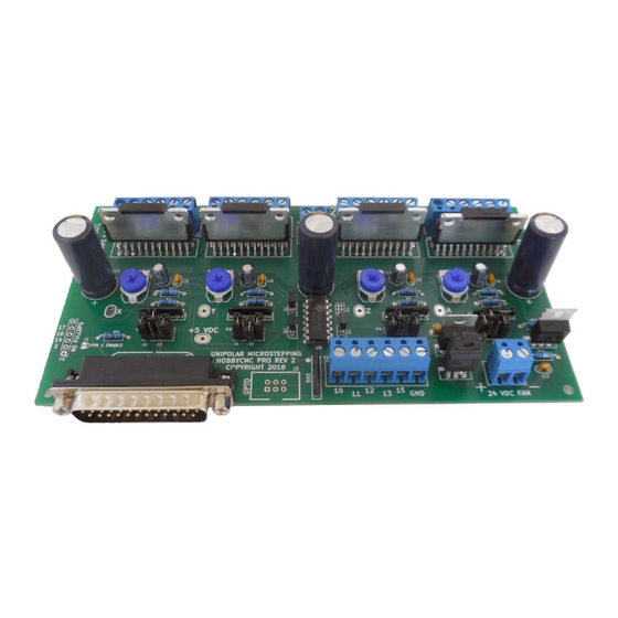
3 axis HobbyCNC PRO Rev1 Chopper Driver Board Kit
Thank you for purchasing our 4 axis HobbyCNC PRO kit. The following information and the step-by-step
instructions will assure complete success and satisfaction. Please read through the following before beginning
any construction to get familiarized with the process. NOTE: Machinery driven with this device can and will
start without warning and may cause injury or even death. The builder of this device assumes sole
responsibility for its use! IF YOU DO NOT AGREE WITH THIS RETURN THE KIT FOR FULL REFUND,
LESS SHIPPING AND HANDLING FEE, BEFORE STARTING ASSEMBLY.
Specifications:
3 Axis Unipolar Chopper control. Individual OR simultaneous control of 2/4 Phase Stepper Motors.
Accepts 5, 6, or 8 wire stepper motors. 4 wire types are not usable.
42 VDC maximum input voltage, 12VDC minimum input voltage.
3.0 Amps Maximum per Phase, 500ma (.5A) minimum. Individually adjustable throughout this range.
1/1, 1/2, 1/4, 1/8, and 1/16 Micro stepping.
Step and Direction Control.
Idle Current Reduction to 50% when idle for 10 seconds. Can change this time delay.
Built In Protection Circuit to help against blown chips on stepper motor short or open connections.
Power On Reset.
On board voltage regulation for 5-volt logic with 24VDC cooling fan from motor power supply.
On board connections for home and limit switches with 10K pullup resistor provided to each.
Minimum of components to make assembly fast and easy.
Tools Required For Assembly:
15-25 Watt soldering pencil
1/32" Rosin core solder
Side cutters
Pliers
Voltmeter
Construction Step by Step:
1. Insert the (6) 10K (R1,R2,R3,R4,R5,R6 Brown Black Black Red Brown) resistors. Simply bend the
leads over to fit the PCB holes (typically .400") and solder in. We ALWAYS use an Ohmmeter to verify
values before soldering in place. Trim the leads. Do not install R7,R8.
2. (3) 100K resistors (R9,R10,R11 Brown Black Yellow Gold) are next. This value gives approximately 10
seconds delay before going into idle current reduction. You can change this delay by substituting a
different value. Expect a 1-second difference for every 10,000 Ohms. 50K would be 5 seconds, 150K
would be 15 seconds etc. 30 seconds (300K seems the limit) Trim the leads. Do not install R12.
3.
(2) 249R resistors (R13,R14 Red Yellow White Black Brown) are now installed. Trim the leads.
4. Install (1) 6.04K (R15 Blue Black Yellow Brown Brown) resistor. Trim the leads.
5. Install (1) 750R (R16 Violet Green Black Black Brown) resistor. Trim the leads.
© 2006-2016 HobbyCNC
50-0004
1
Advertisement
Table of Contents

Summary of Contents for HobbyCNC PRO
- Page 1 3 axis HobbyCNC PRO Rev1 Chopper Driver Board Kit Thank you for purchasing our 4 axis HobbyCNC PRO kit. The following information and the step-by-step instructions will assure complete success and satisfaction. Please read through the following before beginning any construction to get familiarized with the process. NOTE: Machinery driven with this device can and will start without warning and may cause injury or even death.
- Page 2 3 axis HobbyCNC PRO Rev1 Chopper Driver Board Kit 6. Install (6) .1uF (C1,C2,C3,C5,C6,C7) Capacitors. These have NO orientation. Trim the leads. Do not install C4. 7. Solder in (4) 10K Resistor Networks (RN1,RN2,RN3,RN5). Orient the dot with the PCB silkscreened dot.
- Page 3 3 axis HobbyCNC PRO Rev1 Chopper Driver Board Kit that +5.0VDC-+5.2VDC is present will BLOW the driver chips! (U5, R13, and R16 control the +5VDC voltage.) Go no further until +5VDC is achieved with this test. 20. Install (2) MM74HC14N Hex Inverters (U8, U9). Orient the notch as shown in the PCB silkscreen.
- Page 4 3 axis HobbyCNC PRO Rev1 Chopper Driver Board Kit desired amps times .14 equals Vref For any amperage not shown use the following formula: . Again, Idle current reduction MUST be disabled when setting the Vref values. We recommend fan (24VDC) cooling and heat sink at 2A or more.
- Page 5 Steppers will get warm. Also the chopper frequency can be heard in the steppers. This is normal. We welcome your comments and suggestions. Be sure to check our FAQ page hobbycnc.com/faq first. All customer support is handled thru our Yahoo support group. A link was provided at the time of your order.
- Page 6 3 axis HobbyCNC PRO Rev1 Chopper Driver Board Kit © 2006-2016 HobbyCNC 50-0004...
Need help?
Do you have a question about the PRO and is the answer not in the manual?
Questions and answers