Table of Contents
Advertisement
Quick Links
Advertisement
Table of Contents

Related Manuals for Equustek DL6000

Summary of Contents for Equustek DL6000
- Page 1 DL6000 User Manual Revision 1.01 – June 12, 2007...
-
Page 2: Table Of Contents
5.3.1.2 Modbus Master Parameters ..............25 5.3.2 Configuring Modbus Parameters using the DL Offline Manager ....26 5.4 A ........... 29 LLAN RADLEY ETWORK ONFIGURATION 5.4.1 DH+ Node Address ..................29 #286-5489 Byrne Rd., Burnaby, BC, V5J3J1, Canada Phone: 888-387-3787 or 604-266-8547 www.equustek.com... - Page 3 ABLE 7.3 DH+ C ......................35 ABLE 7.4 DH-485 C ....................35 ABLE 8 DL6000 TYPICAL APPLICATIONS ............36 8.1 DL6000-MEDH+ ....................36 9 FREQUENTLY ENCOUNTERED PROBLEMS ........37 9.1 D DL6000 ..........37 EVICE NSTALLER CANNOT FIND THE 9.2 C DL6000-MEDH+ ....
-
Page 4: General Operation And Applications
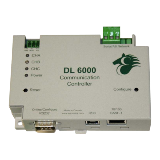
XPORT_MBTCP Ethernet Microprocessor with our proven A-B interface. The DL6000 comes with a RJ-45 Connector for the 10/100 Base-T Ethernet link, and a 3 pin Phoenix plug for connection to A-B networks. Power is supplied via a 3 pin Phoenix type plug which allows for 9-27 Volts DC to be connected. -
Page 5: Hardware Specifications And Layout
Configuration and Reset Pushbuttons go into BIOS features and Flash Setup and do a full Hardware Reset. Operating Parameters are stored in Non-Volatile Serial EEPROM. The DL6000 uses FLASH upgradeable firmware from either the supplied EQ32 configuration program or once can use a HyperTerminal type program set to 19200,N,8,1 and XON/XOFF flow control. -
Page 6: Physical Specifications
The RESET pushbutton is on the left side, the Configure pushbutton is on the right side. The bottom side of the DL6000 has the following connectors: Going Left to Right. 9 Pin DB9 connector for MODBUS Configuration, the BIOS and Firmware. -
Page 7: Mode Of Operation
Mode of Operation Online Mode of Operation Online Mode is the normal operating Mode of the DL6000. In this mode the Channels are now configured as they are defined by the A-B Network and Configuration. The DL6000 is ready to interface your equipment. - Page 8 Firmware Version Once selected the current DL6000 model and version numbers will be displayed. Can be used to check the correct firmware was burnt into the Flash or if the DL6000 has the most up to date firmware in the Flash.
-
Page 9: Switch And Led Indicator Functions
The Reset pushbutton will perform a complete hardware reset of the DL6000. It is identical to a complete power cycle and will cause the DL6000 to go through its LED start-up sequence as defined in Section 5.2.1. A complete hardware reset is needed on changing any online operating parameters. -
Page 10: Normal On-Line Operation
4.2.2 Normal On-line Operation The following is a description of the normal operation of the LED’s on the DL6000. LEFT LED’s Description of Operation Power Green Indicates Power is being supplied to the DL6000. (Ethernet) Flashes GREEN for 0.5 seconds when a character is Received or Transmitted. -
Page 11: On-Line, Power-Up And Reset Errors
A-B Network There is a duplicate node on the A-B network. The Flashing RED DL6000 has been assigned a node address that is already in use. 4.2.4 Off-Line Modes The following table describes the meaning of LED patterns in the different Off-Line modes of operation. -
Page 12: Configuration
Used to map Modicon registers/coils to Allan-Bradley data files with the DL6000-MEDH+ or MEDH-485. After the IP address of the DL6000 is assigned, you must then telnet to the DL6000 to setup the internal communications between the Lantronix daughter board and the DL6000 motherboard. - Page 13 The following steps are used to assign an IP address to the DL6000. 1. Click on the Search button to have the Device Installer find the DL6000. If the Device Installer finds the DL6000, the device should appear. If the device cannot be found then follow the instructions at the end of the IP Address section.
- Page 14 3. Enter the desired IP address, subnet mask, and default gateway (if required) and click Next. 4. To assign the chosen IP address to the DL6000, click the Assign button. #286-5489 Byrne Rd., Burnaby, BC, V5J3J1, Canada Phone: 888-387-3787 or 604-266-8547...
-
Page 15: Device Not Found
5.1.1.1 Device Not Found If for some reason the Device Installer cannot find the DL6000 on the Ethernet network, follow the steps below. 1. Click the Assign IP button and the following screen will appear. -
Page 16: Telnet
2. Enter MAC address of the DL6000 and click Next. The MAC Address can be found on the bottom of the DL6000. The Device Installer should now find the device. Now follow the steps at the beginning of the IP Address section to assign an IP address. If for some reason the device still cannot be found, see section 9.1 Device Installer... - Page 17 Press the Connect button and when prompted, press the Enter key with in 5 seconds to bring up the main menu. After pressing Enter, you will get the following menu. #286-5489 Byrne Rd., Burnaby, BC, V5J3J1, Canada Phone: 888-387-3787 or 604-266-8547 www.equustek.com...
-
Page 18: Modbus Tcp Telnet Settings
C:\>telnet 192.168.2.2 9999 Below are the Telnet settings for the different DL6000 models. After starting a telnet session, you must press the Enter key with in 5 seconds to bring up the main menu. 5.1.3 Modbus TCP Telnet Settings The following menu will appear after starting a telnet session. -
Page 19: Modbus Master Settings
115200. 3. Press S to save the new settings and end the telnet session. 4. Press the reset button on the DL6000 to put it online. 5.1.3.1 Modbus Master Settings To set the proper Telnet settings, follow the steps below: 1. -
Page 20: Eq32 Configuration Software
Allan-Bradley networks. 5.3.1 Configuring Modbus Parameters To configure your DL6000, open the EQ32 Configuration Software and follow the steps shown below. The following welcome screen will appear when the software is opened. #286-5489 Byrne Rd., Burnaby, BC, V5J3J1, Canada Phone: 888-387-3787 or 604-266-8547 www.equustek.com... - Page 21 1. From the Welcome screen, select the DL6000 model. The Main Menu should appear as shown below. 2. Select the COM port that you have connected to the DL6000 and Click on the Configure button. The Configuration Menu for the DL6000 will appear as shown below.
-
Page 22: Modbus Slave Parameters
3. The configuration for the Modbus Slave is different than the Modbus Master. Follow the instructions for the mode that the mode that the DL6000 will be configured for. 5.3.1.1 Modbus Slave Parameters 4. For the Modbus Device Type, select Slave to bring up the configurable slave parameters. - Page 23 “DL3500-DH+ Modbus Slave” which can be found on the CD that came with the DL6000 or downloaded from www.equustek.com. The setup of the translation table is the same for both the DL3500 and the DL6000, to help with mapping you can use Equustek program called (Allan-Bradley to Modbus Mapping Program), it can be found on the CD and on our website as well.
- Page 24 10. After selecting one of the three options, click Finish to perform the selected action. If you have chosen to download the configuration, make sure you received message shown below before pressing reset to put the DL6000 online. #286-5489 Byrne Rd., Burnaby, BC, V5J3J1, Canada Phone: 888-387-3787 or 604-266-8547 www.equustek.com...
-
Page 25: Modbus Master Parameters
For a more detailed explanation with examples, see the DL3500 application note “DL3500-DH+ Modbus Master” which can be found on the CD that came with the DL6000 or downloaded from www.equustek.com. The decoding method used by the DL6000 is the same as the DL3500. -
Page 26: Configuring Modbus Parameters Using The Dl Offline Manager
The DL Offline Manager can also be used to setup the Modbus Slave parameters for the DL6000. There is currently no ability to configure the Modbus Master settings. If you are using the DL6000 as a Modbus Master, you will need to use the method described above. - Page 27 AT Any time hit <ENTER> To Keep existing parameter value Hit <ENTER> To continue, <ESC> to exit 2. Press Enter to continue. You will then be asked to select a PLC type that the DL6000 will be communicating to. Select A-B PLC TYPE: SLC/Micrologix Enter 0 for PLC5, 1 for PLC3 or 2 for SLC or Micrologix or <ENTER>...
- Page 28 Press Y to accept the current parameters, or N to discard the current parameters. 5. After this is done, close the EQ32 Configuration software and press Reset on the DL6000 to put it online. #286-5489 Byrne Rd., Burnaby, BC, V5J3J1, Canada Phone: 888-387-3787 or 604-266-8547 www.equustek.com...
-
Page 29: Allan-Bradley Network Configuration
The DH+ network allows up to 64 nodes on a network with addresses ranging from 0 to 63 decimal. The DL6000 DH+ node address is determined from the last octet of the IP address assigned to the unit. The following table shows how the DH+ node address is determined from the last octet of the IP address. -
Page 30: Dh-485 Node Address
The DH-485 network allows up to 32 nodes on a network with addresses ranging from 0 to 31 decimal. The DL6000 DH-485 node address is determined from the last octet of the IP address assigned to the unit. The following table shows how the DH-485 node address is determined from the last octet of the IP address. -
Page 31: Firmware Upgrade
1. Open the EQ32 Configuration and select DL6000 Models. You will see the following screen. 2. Select the COM port attached to the DL6000 and click the DL Offline Manager button. You will be prompted to press the configure button on the DL6000. The following menu will be shown in a new window. - Page 32 BIOS MANAGER for DL6000-1.00- Jun 16,06 (c) Equustek Solutions Inc. 2006 MAIN MENU 1 - Restore EEPROM 2 - WRITE new Firmware 3 - Memory DUMP 4 - OFF-LINE Diagnostics 5 - DEBUG Mode 6 - FIRMWARE Version 7 – ONLINE...
- Page 33 5. When the Send Flash System File button is pressed, a message box will appear asking if the WRITE new Firmware option was selected. Click Yes to continue. 6. Select the desired firmware file and the DL6000 will begin upgrading the firmware. Upon a successful install, the following text will appear.
-
Page 34: Wiring Diagrams
RS-232 null modem cable which is used to connect serially to the DL6000. DL6000 Pinout Diagram Below is an image of the DL6000 that shows the numbering of the DH+/DH-485 connector. Pin 1 is located closest to the power connector. -
Page 35: Rs-232 Null Modem Cable
The RS-232 null modem cable is used to serially connect to the DL6000 in order to use the DL Offline Manager or configure the device using the EQ32 Configuration Software. DH+ Cable Below is a diagram of the DL6000 DH+ connector. Pin 1 is the pin closest to the power connector. DH-485 Cable Below is a diagram of the DL6000 DH-485 connector. -
Page 36: Dl6000 Typical Applications
DL6000 Typical Applications The DL6000 is designed to be used in applications using Ethernet to communicate with devices on a DH+ or DH-485 network. Some of the typical applications that use the DL6000 are shown in this section. DL6000-MEDH+ The following example shows a SCADA server using a DL6000 to acquire data from PLC’s and devices on the DH+ network. -
Page 37: Frequently Encountered Problems
DL6000 which can be located on the bottom of the unit (denoted by aa-bb-cc-dd-ee- ff). 4. Open a telnet session to the DL6000 using port 1. This is done by typing the following at the command prompt. telnet xxx.xxx.xxx.xxx 1 #286-5489 Byrne Rd., Burnaby, BC, V5J3J1, Canada... -
Page 38: Cannot Communicate To Dh+ Node Using The Dl6000-Medh
5. Finally open another telnet session but this time to port 9999 as follows. telnet xxx.xxx.xxx.xxx 9999 6. Set the IP address of the DL6000 by changing the Network or Server settings from the main menu of the telnet session. The IP address assigned here will become the permanent IP address of the DL6000. -
Page 39: Appendix A: Tcp/Ip Tutorial
Appendix A: TCP/IP Tutorial This section is design to guide you to gain a brief understanding to TCP/IP addressing mechanism and the meaning behind the DL6000 IP configurations. TCP/IP suite is the most commonly used Ethernet communication protocol in both industrial and commercial networking applications. -
Page 40: Subnet Mask
255 or 0 in the Subnet Mask segments for network customizations. However, this advance TCP/IP application is beyond the scope of this tutorial. #286-5489 Byrne Rd., Burnaby, BC, V5J3J1, Canada Phone: 888-387-3787 or 604-266-8547 www.equustek.com... -
Page 41: Valid Ip Addresses
IP addresses with the first segment ranging from 128 to 191, and subnet mask 255.255.0.0. Class C IP Address IP addresses with the first segment ranging from 192 to 223, and subnet mask 255.255.255.0. #286-5489 Byrne Rd., Burnaby, BC, V5J3J1, Canada Phone: 888-387-3787 or 604-266-8547 www.equustek.com... - Page 42 IP address regulations, in which the IP address / Subnet Mask couple is interpreted differently than in classful IP address. Detail information on class-less IP address regulations is out of the scope of this tutorial. #286-5489 Byrne Rd., Burnaby, BC, V5J3J1, Canada Phone: 888-387-3787 or 604-266-8547 www.equustek.com...
Need help?
Do you have a question about the DL6000 and is the answer not in the manual?
Questions and answers