Table of Contents
Advertisement
Quick Links
Including Protection, Performance, and Inlet Shut-off Valve Packages
Ambler, PA 19002
www.bradfordwhite.com
Tech. Service ..........................(800) 334-3393
Service Parts ..........................(800) 538-2020
Warranty Department .............(800) 531-2111
INSTALLATION & OPERATION MANUAL
PLACE THESE INSTRUCTIONS ADJACENT TO WATER HEATER AND NOTIFY OWNER TO KEEP FOR FUTURE REFERENCE
ACCESSORY MODULE
With Troubleshooting Guide
This
manual
must
conjunction with the Installation and
Operation Manual for the water heater.
Do not store or use gasoline or other
-
flammable vapors and liquids in the
vicinity of the water heater or any
other appliance
-
What to do if you smell gas:
•
Do not try to light any appliance.
•
Do not touch any electrical switch;
do not use any phone in your
building.
•
Immediately call your gas supplier
from a neighbor phone. Follow
the gas supplier instructions.
•
If you cannot reach your gas
supplier, call the fire department.
-
For your family comfort, safety and
convenience, it is recommended these
packages be installed and serviced by
a plumbing professional.
-
Read and understand the water heater
manual before installing or operating
the Accessory Module and its
associated packages.
238-47878-00B 04/10
be
used
in
Advertisement
Table of Contents

Summary of Contents for Bradford White ACCESSORY MODULE
- Page 1 Service Parts ......(800) 538-2020 Warranty Department .....(800) 531-2111 Read and understand the water heater manual before installing or operating the Accessory Module and its associated packages. INSTALLATION & OPERATION MANUAL With Troubleshooting Guide PLACE THESE INSTRUCTIONS ADJACENT TO WATER HEATER AND NOTIFY OWNER TO KEEP FOR FUTURE REFERENCE...
- Page 2 For easier installation, the Integrated Mixing Device and Inlet Shut-off Valve should be installed first. Accessory Module: The Accessory Module is an electronic component that allows the water heater gas control to be connected to the Protection, Performance, and Inlet Shut-off Valve Packages. Accessory Module:...
- Page 3 Important Information Protection Package (sold separately): Contains: o Leak sensor (2 piece) o Wire holders o Dam o Wire ties o Leak sensor wire harness o Screws Features: o Senses a collection of water near the water heater o Sounds the alarm to alert homeowners when a water heater leak is detected and verified o Alarm is re-settable and can be temporarily silenced o Durable construction...
- Page 4 Important Information READ CAREFULLY The following terms are used throughout this manual to bring attention to the presence of hazards at various risk levels, or to important information concerning product life. DANGER CAUTION Indicates an imminently hazardous Indicates potentially hazardous situation, situation, which, if not avoided, will result which, if not avoided, may result in in death, serious injury or substantial...
- Page 5 WARNING Do not operate the water heater or Accessory Module without the Accessory Module cover in place. Do not operate the water heater or Setback Control without the Setback Control Junction Box Assembly cover in place.
-
Page 6: Table Of Contents
Table of Contents Page Tools Required.................... 7 Package Components................. 8 Accessory Module ................8 Protection Package ................. 9 Performance Package..............10 Inlet Valve Shut-off Package ............11 Wiring Diagram ................... 12 Accessory Module Installation..............13 Setback Control Installation ................ 27 Integrated Mixing Device - IMD .............. -
Page 7: Tools Required
Tools Required Slotted Screwdriver Philips Screwdriver 1/8” Drill bit Drill Needle nose pliers Pipe dope Adjustable wrench Caulk gun RTV sealant (silicone) Pipe cutter Propane torch Solder Flux Wire Cutters Wire Strippers Fine Point Marker... -
Page 8: Package Components
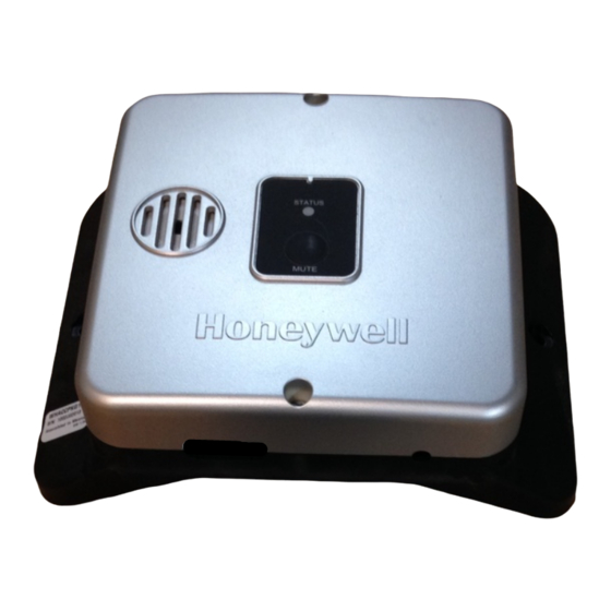
Package Components Accessory Module FOR USE WITH THE FOLLOWING GAS VALVES: ACCESSORY MODULE DIAGNOSTIC CODES 222-47463-01 222-47466-02 222-47463-02 222-46402-01 LED STATUS ACCESSORY MODULE STATUS 222-47464-01 222-46402-02 222-47464-02 222-46990-01 COLOR PATTERN 222-47465-01 222-46990-02 GREEN LED on continuously. Power on (no fault). -
Page 9: Protection Package
Package Components Protection Package Table 2 Protection Package Description Quantity Leak Sensor Bracket Leak Sensor Housing Screws Leak Sensor Wire Harness Wire Holders Wire Ties... -
Page 10: Performance Package
Package Components Performance Package Table 3 Performance Package Description Quantity Setback Control Wire Harness Integrated Mixing Device, IMD - Cold Water Tee - Mixing Valve - 8” Flexible Connector - 11” Flexible Connector - Instruction & Operation Manual - Thermo-strip Setback Control (batteries included) Wire Ties Setback Control Junction Box Assembly... -
Page 11: Inlet Valve Shut-Off Package
Package Components Inlet Shut-off Valve Package Table 4 Inlet Shut-off Valve Description Quantity Inlet Shut-off Valve with Integrated Wire Harness ¾” x 1” NPT Brass Bushings Wire Ties -11-... -
Page 12: Wiring Diagram
Wiring Diagram -12-... -
Page 13: Accessory Module Installation
In the following section, the instructions detail how to install the Accessory Module. Properly locating and mounting the Accessory Module is required. Unpack the Accessory Module Step 1: Remove the Accessory Module and its components from their packaging, as shown in Figure 1. Figure 1 Determine the Gas Control Wire Harness Step 2: If the gas control uses an intermittent pilot, the WV4460 wire harness must be used. - Page 14 Locate the Accessory Module Step 4: The Accessory Module must be mounted to the left of the water heater gas control. Hold the Accessory Module to the water heater jacket as high as possible and practical. Do not cover any safety or warning labels on the water heater.
- Page 15 Accessory Module Installation Mark the Location of the Accessory Module Step 5: Using a marker, mark the location of the Accessory Module screw holes. This is shown in Figure 5. Water Heater Accessory Module Marker Figure 5 Set the Accessory Module Aside Step 6: Remove the Accessory Module from the water heater jacket, as shown in Figure 6.
- Page 16 Heater Marked drill locations Drill Figure 7 Position the Accessory Module Step 8: Put the Accessory Module up against the water heater jacket and position it to the pre-drilled holes. This is shown in Figure 8. Pre-drilled holes Accessory Module...
- Page 17 Accessory Module Installation Mounting the Accessory Module Step 9: Using (2) of the included Philips head screws, screw the Accessory Module to the water heater jacket, as shown in Figure 9. Water Heater jacket Accessory Module Philips head screwdriver Figure 9 Apply the Necessary Labels Step 10: Apply both the wiring diagram and diagnostic labels.
- Page 18 Accessory Module Installation Remove the Accessory Module Cover Step 11: Using a Philips head screwdriver, loosen both screws on the Accessory Module cover, as shown in Figure 11. The cover screws are permanently retained and cannot be completely removed. Retain the cover for later use.
- Page 19 Accessory Module Installation Assemble the Transformer and its Wire Harness Step 13: Take one end of the transformer wire harness and slide each fork terminal under one of the screws. This is shown in Figure 13. Plug-in Transformer Transformer slotted screws...
- Page 20 Accessory Module Installation Prepare to Connect the Transformer Wire Harness to the Accessory Module Step 15: Loosen the (2) Philips head screws on the Accessory Module, labeled “R1” and “C1.” This is shown in Figure 15. Accessory Module Philips head...
- Page 21 Step 18: If the water heater gas control has an intermittent pilot (WV4460 gas control), loosen the (3) screws on the Accessory Module labeled “D/1,” “R/2,” and “C/3.” This is shown in Figure 18. If the water heater has a standing pilot, proceed to Step 25.
- Page 22 Accessory Module Installation Assemble the WV4460 Wire Harness and Accessory Module Step 19: Insert the red wire, from the WV4460 wire harness, under the screw labeled “D/1.” This is shown in Figure 19. Accessory Module WV4460 Wire Harness Red Wire...
- Page 23 Accessory Module Installation Assemble the WV4460 Wire Harness and Accessory Module – cont’d Step 21: Insert the black wire, from the WV4460 wire harness, under the screw labeled “R/2.” This is shown in Figure 21. Accessory Module WV4460 Wire Harness Red Wire...
- Page 24 Accessory Module Installation Assemble the WV4460 Wire Harness and Accessory Module – cont’d Step 23: Insert the white wire, from the WV4460 wire harness, under the screw labeled “C/3.” This is shown in Figure 23. Accessory Module WV4460 Wire Harness Red Wire...
- Page 25 Connect the Accessory Module to the WV8840 Wire Harness Step 25: Insert one end of the WV8840 wire harness over the edge of the Accessory Module circuit board. This connection point is on the bottom right hand side of the circuit board, and it is shown in Figure 25.
- Page 26 Step 27: Push the plastic connector on the WV8840 wire harness into the recessed area on the bottom side of the WV8840 gas control. This is shown in Figure 27. WV8840 Gas Control WV8840 Wire Harness Figure 27 The Accessory Module installation is complete. Proceed to the installation sections for the other purchased packages. -26-...
-
Page 27: Setback Control Installation
Setback Control Installation In the following section, the instructions detail how to install the Setback Control on the water heater. The Accessory Module must be installed for the Setback Control to work with the water heater gas control. Unpack the Setback Control Junction Box Assembly Step 1: Remove the Setback Control Junction Box Assembly and its components from their packaging. - Page 28 Setback Control Installation Remove the Setback Control Battery Holder Step 3: Depress the top side of the battery holder and remove it. This is shown in Figure 30. Battery Holder Setback Control Figure 30 Install the Setback Control Batteries Step 4: Install the (2) supplied AAA batteries into the battery holder of the Setback Control, as shown in Figure 31.
- Page 29 Setback Control Installation Install the Setback Control Battery Holder Step 5: Install the Setback Control Battery Holder, just as it was installed prior to Step 3. This is shown in Figure 32. Battery Holder Setback Control Figure 32 Remove the Protective Plate Step 6: Remove the Setback Control protective plate from the Setback Control by pulling these items apart.
- Page 30 Setback Control Installation Locate the Setback Control Junction Box Assembly Step 7: Place the Setback Control Junction Box Assembly on top of the water heater. This assembly must face the front of the water heater, and it must be located close to the centerline of the water heater. This is shown in Figure 34.
- Page 31 Setback Control Installation Remove the Setback Control Junction Box Assembly Step 9: Remove the Setback Control Junction Box Assembly from the top of the water heater, as shown in Figure 36. Setback Control Junction Box Assembly Top of Water Heater Figure 36 Drill the Setback Control Junction Box Assembly Mounting Holes Step 10: Using a 1/8”...
- Page 32 Setback Control Installation Position the Setback Control Junction Box Assembly Step 11: Put the Setback Control Junction Box Assembly back on top of the water heater and position it to the pre-drilled holes. This is shown in Figure 38. Setback Control Junction Box Assembly Top of Water Heater...
- Page 33 Setback Control Installation Install the Setback Control Step 13: Snap the Setback Control into the backplate on the Setback Control Junction Box Assembly. Align the Setback Control to the backplate, and press until it is fully seated. This is shown in Figure 40. Setback Control Junction Box Assembly Backplate Already...
- Page 34 Setback Control Installation Connect the Setback Control Wire Harness to the Accessory Module Step 15: If the water heater gas control has an intermittent pilot (WV4460 gas control), the connection, “D/1,” is already being used. This same connection point is used to connect the Setback Control. Loosen the screw “D/1.”...
- Page 35 Figure 44 Assemble the Setback Control Wire Harness and Accessory Module – cont’d Step 18: If the water heater gas control has an intermittent pilot (WV4460 gas control), the connection, “R/2,” is already being used. This same connection point is used to connect the Setback Control. Loosen the screw “R/2.”...
- Page 36 Setback Control Installation Assemble the Setback Control Wire Harness and Accessory Module – cont’d Step 19: Insert the black wire, from the Setback Control wire harness, under the screw labeled “R/2.” If the water heater has a WV4460 gas control, the gas control wire harness black wire must be retained underneath this screw also.
- Page 37 Setback Control Installation Assemble the Setback Control Wire Harness and Accessory Module – cont’d Step 21: If the water heater gas control has an intermittent pilot (WV4460 gas control), the connection, “C/3,” is already being used. This same connection point is used to connect the Setback Control. Loosen the screw “C/3.”...
- Page 38 Setback Control Installation Connect the Setback Control Wire Harness and Accessory Module – cont’d Step 23: Tighten the screw labeled “C/3,” as shown in Figure 50. Accessory Module WV8840 Wire Harness (if installed) WV4460 Wire Harness Red Wire (if installed)
-
Page 39: Integrated Mixing Device - Imd
Integrated Mixing Device - IMD Refer to the instructions included with Integrated Mixing Device (IMD), on how to install and operate the IMD. Figure 51 shows the contents included with the integrated mixing device. Figure 51 CAUTION The piping diagram supplied with the water heater must be followed. -39-... -
Page 40: Leak Sensor Installation
Leak Sensor Installation In the following section, the instructions detail how to install the Leak Sensor. The Accessory Module must be installed for the Leak Sensor to work with the water heater gas control. The leak sensor can take up to 15 minutes to sense and verify a water heater tank leak. Unpack the Leak Sensor and its Components Step 1: Remove the Leak Sensor and its components from their packaging, as shown in Figure 52. - Page 41 Connector Figure 54 Prepare the Accessory Module for the Leak Sensor Step 4: Loosen the screw labeled “C1,” as shown in Figure 55. Ensure that the Transformer wire harness wire going to this same location remains inserted under this screw.
- Page 42 Leak Sensor Resistor Transformer Wire Harness Figure 56 Remove the Leak Sensor Resistor Step 6: Using needle nose pliers, remove the Leak Sensor resistor from the Accessory Module and discard. This is shown in Figure 57. Accessory Module Leak Sensor Resistor...
- Page 43 Leak Sensor Installation Assemble the Leak Sensor Wire Harness and the Accessory Module Step 7: Insert the red wire, from the Leak Sensor wire harness, under the screw labeled “C1.” This is shown in Figure 58. Ensure that the wire from the Transformer wire harness at this location is retained under this screw.
- Page 44 Leak Sensor Installation Assemble the Leak Sensor Wire Harness and the Accessory Module – cont’d Step 9: Insert the black wire, from the Leak Sensor wire harness, under the screw labeled “LK.” This is shown in Figure 60. Accessory Module...
- Page 45 Leak Sensor Installation Position the Leak Sensor Step 11: Position the Leak Sensor up against the water heater jacket, as shown in Figure 62. The Leak Sensor must be positioned to the left of the water heater gas control. The Leak Sensor must sit flat on the floor or in the drain pan.
- Page 46 Leak Sensor Installation Remove the Leak Sensor Step 13: Remove the Leak Sensor from the water heater jacket, and set it aside. This is shown in Figure Leak Sensor Wire Harness Leak Sensor Figure 64 Drill the Leak Sensor Mounting Hole Step 14: Using a 1/8”...
- Page 47 Leak Sensor Installation Position the Leak Sensor Step 15: Put the Leak Sensor back in position against the water heater jacket and position to the pre- drilled hole, as shown in Figure 66. Water Heater Jacket Leak Sensor Wire Harness Leak Sensor Figure 66 Mount the Leak Sensor...
- Page 48 Leak Sensor Installation Position the Dam Step 17: Position the dam around the water heater, so it surrounds the water heater and corrals a water heater tank leak towards the Leak Sensor. This is shown in Figure 68. Leak Sensor Figure 68 WARNING The dam must be mounted against the floor or it will not hold any water.
-
Page 49: Inlet Shut-Off Valve Installation
Leak Sensor has sensed and verified a water heater tank leak has occurred. The Accessory Module and Leak Sensor must be installed for the Inlet Shut-off Valve to work with the water heater gas control. - Page 50 Inlet Shut-off Valve Installation Determine if Bushings are Necessary Step 3: If the water heater uses a 3/4” NPT thread water inlet, the (2) included 3/4” x 1” NPT bushings must be used. Proceed to Step 4. Otherwise, proceed to Step 6. Prepare Bushings for Installation Step 4: Apply pipe dope (suitable for potable water use) to the threads of the bushings, as shown in Figure 71.
- Page 51 Inlet Shut-off Valve Installation Install the Bushings Step 5: Thread the bushings into each end of the Inlet Shut-off Valve, as shown in Figure 72. Inlet Shut-off Valve Bushings Figure 72 Install the Inlet Shut-off Valve Step 6: Thread the Inlet Shut-off Valve onto the water heater inlet (cold). Or, if an integrated mixing device is used, thread the Inlet Shut-off Valve onto the IMD inlet.
- Page 52 The piping diagram supplied with the water heater must be followed. Connect the Inlet Shut-off Valve Harness to the Accessory Module Step 8: Loosen the (3) screws on the Accessory Module labeled “C2,” “NO,” and “NC.” This is shown in Figure 75.
- Page 53 Inlet Shut-off Valve Installation Assemble the Inlet Shut-off Valve Wire Harness and the Accessory Module Step 9: Insert the blue wire, from the Inlet Shut-off Valve wire harness, under the screw labeled “C2,” as shown in Figure 76. Accessory Module...
- Page 54 Inlet Shut-off Valve Installation Assemble the Inlet Shut-off Valve Wire Harness and the Accessory Module – cont’d Step 11: Insert the brown wire, from the Inlet Shut-off Valve wire harness, under the screw labeled “NO,” as shown in Figure 78.
- Page 55 Inlet Shut-off Valve Installation Assemble the Inlet Shut-off Valve Wire Harness and the Accessory Module – cont’d Step 13: Insert the black wire, from the Inlet Shut-off Valve wire harness, under the screw labeled “NC,” as shown in Figure 80.
-
Page 56: Remote Mounting The Setback Control
Remote Mounting the Setback Control In the following section, the instructions detail how to Remote Mount the Setback Control. Remove the Setback Control from the Backplate Step 1: Remove the Setback Control from the backplate attached to the Setback Control Junction Box Assembly. - Page 57 Remote Mounting the Setback Control Mount the Protective Plate Step 3: Mount the Setback Control Protective Plate in a desired location. Be sure that the Setback Control will not be direct sunlight, as the display may be difficult to read. This is shown in Figure 84. Drill Wall Protective...
- Page 58 Remote Mounting the Setback Control Label the Wires for Remote Mounting Step 5: Label the (3) cut wires (A), (B), and (C) respectively. Label both ends of the wires. This is shown in Figure 86. Masking tape can be used to label the wires. Label Each Wire Figure 86...
- Page 59 Remote Mounting the Setback Control Install Wire (A) – Backplate Step 7: Using wire (A), insert one end into the top terminal location on the backplate (located on the Setback Control Junction Box Assembly). This is shown in Figure 88. Be sure that the wire already located in this location is not dislodged.
- Page 60 Remote Mounting the Setback Control Install Wire (B) – Backplate Step 9: Using wire (B), insert one end into the middle terminal location on the backplate (located on the Setback Control Junction Box Assembly). This is shown in Figure 90. Be sure that the wire already located in this location is not dislodged.
- Page 61 Remote Mounting the Setback Control Install Wire (C) – Backplate Step 11: Using wire (C), insert one end into the bottom terminal location on the backplate (located on the Setback Control Junction Box Assembly). This is shown in Figure 92. Be sure that the wire already located in this location is not dislodged.
- Page 62 Remote Mounting the Setback Control Route Wires to Protective Plate Step 13: Route all three wires to the Setback Control Protective Plate. Install Wire (A) – Protective Plate Step 14: Using wire (A), insert one end into the top terminal location on the Protective Plate. This is shown in Figure 94.
- Page 63 Remote Mounting the Setback Control Fasten Wire (A) into its Designated Location – Protective Plate Step 15: Tighten the slotted screw in the top terminal location on the Protective Plate. This is shown in Figure 95. Wire (A) Protective Plate Slotted head screwdriver Figure 95...
- Page 64 Remote Mounting the Setback Control Fasten Wire (B) into its Designated Location – Protective Plate Step 17: Tighten the slotted screw in the middle terminal location on the Protective Plate. This is shown in Figure 97. Wire (A) Wire (B) Protective Plate Slotted head...
- Page 65 Remote Mounting the Setback Control Fasten Wire (C) into its Designated Location – Protective Plate Step 19: Tighten the slotted screw in the bottom terminal location on the Protective Plate. This is shown in Figure 99. Wire (A) Wire (B) Protective Wire (C) Plate...
- Page 66 Remote Mounting the Setback Control Install Cover Plate Step 21: Snap the Setback Cover Plate onto the backplate (located on the Setback Control Junction Box Assembly). This is shown in Figure 101. Cover Plate Setback Control Junction Box Assembly Backplate Figure 101 Remote Mounting the Setback Control is complete.
-
Page 67: Start-Up Procedure
Start-up Procedure In the following section, the instructions detail the Start-up Procedure for the Accessory Module, once any or all of its packages are completely installed. Route the Wire Harnesses in the Accessory Module Step 1: Route all of the wire harnesses out of the openings in the bottom and left side of the Accessory Module. - Page 68 Start-up Procedure Fix the Accessory Module Cover in Place Step 3: Tighten both Accessory Module cover screws, as shown in Figure 104. Philips head screwdriver Accessory Module Figure 104 Route the Various Wire Harnesses Step 4: Route the wire harnesses along the jacket and group them using the included wire ties. This is shown in Figure 105.
- Page 69 Start-up Procedure Fix the Wire Harnesses Step 5: Using the included wire holders, fix the wire harnesses to the water heater jacket only to the left of the water heater gas control, as shown in Figure 106. Wire holders can be used to fix the wire harnesses to the water heater jacket only to the left of the water heater gas control.
- Page 70 Step 8: Watch the LED on the Accessory Module, and observe as it progresses through the Start-up Sequence. This is shown in Figure 109. If the LED on the Accessory Module goes green at the end of the Start-up Sequence, proceed to Step 11 on page 72.
- Page 71 Action Required for Improper Start-up Sequence Step 9: If the Start-up Sequence results in a red LED strobe, the internal electronics on the Accessory Module failed. The Accessory Module must be replaced. This is shown in Figure 110. Observe LED...
- Page 72 Start-up Procedure Verify Inlet Shut-off Valve Operation (if installed) Step 11: If the Inlet Shut-off Valve is installed, the valve will open during the Start-up Sequence. Verify that the valve is open by drawing water from a faucet (specifically hot water). This is shown in Figure 111. Figure 111 Program the Setback Control (if installed) Step 12: Refer to the instructions included with the Setback Control on how to program the control.
-
Page 73: Diagnostic Codes
2. The Setback Control wire harness has some wrong connections. Replace the wire harness. NOTICE The leak detection alarm can be muted. Press the button on the front of the Accessory Module to mute this alarm for 1 day. CAUTION Perform a cycle of the Test Mode on the Accessory Module on a regular basis. -
Page 74: Notes
Notes -74-... -
Page 75: Warranty
1. Contact either the installer or dealer, or inconvenience or other incidental or consequential costs. 2. Contact us: Costs associated with the replacement BRADFORD WHITE CORPORATION and/or repair of the unit, including: WARRANTY SUPPORT GROUP any freight, shipping or delivery charges... - Page 76 Ambler, PA For U.S. and Canada field service, contact your professional installer or local Bradford White sales representative. Sales/800-523-2931 Fax/215-641-1670 Parts Fax/215-641-2108 Technical Support/800-334-3393 Fax/269-795-1089 Warranty/800-531-2111 Fax/269-795-1089 International: Telephone/215-641-9400 Telefax/215-641-9750 Mississauga, ON Sales/866-690-0961 905-238-0100 Fax/905-238-0105 Technical Support/800-334-3393 Email: parts@bradfordwhite.com techserv@bradfordwhite.com...
Need help?
Do you have a question about the ACCESSORY MODULE and is the answer not in the manual?
Questions and answers