Advertisement
Quick Links
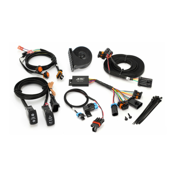
ATS-POL-GBU/RCBU Turn Signal System
Thank you for purchasing XTC Power Products Automatic Self -Canceling Turn Signal System. Our Easy Install Turn
Signal System is unique from the other kits on the market. This kit is from our Plug & Play™ product line, no wires
to cut, no crimping with only power, ground and plugs into the OEM Tail Light Harness, utilizing the brake lights as
Brake and Turn Signals.
Since this System fits more than one UTV, the below instructions cover basic install instructions. Please
remember that the Control Module and switches can be mounted in many places, we only give suggestions. We
only interface with the OEM wiring at the Rear Light Harness and the Power Busbar Plugs in under the hood.
We are referencing 2 models, they are the same except for the Rear Harness.
The ATS-POL-GBU has a Rear Harness with a 4 Way Connector.
The ATS-POL-RCBU has a Rear Harness with an 8 Way Connector.
Please read the instructions fully and familiarize yourself with t he components before starting the install.
The diagram below shows the overall system layout.
Advertisement

Related Manuals for XTC ATS-POL-GBU

Summary of Contents for XTC ATS-POL-GBU
- Page 1 ATS-POL-GBU/RCBU Turn Signal System Thank you for purchasing XTC Power Products Automatic Self -Canceling Turn Signal System. Our Easy Install Turn Signal System is unique from the other kits on the market. This kit is from our Plug & Play™ product line, no wires to cut, no crimping with only power, ground and plugs into the OEM Tail Light Harness, utilizing the brake lights as Brake and Turn Signals.
- Page 2 1. Remove the hood and Dash cover if installing under the dash, and the center console or panel 2. Mount the Control Module using the self-tapping screw provided. The Control Box may be mounted under the dash or under the hood. Make sure before mounting the Control Module, that the turn switch harness can make it to the dash where you want the switches mounted.
- Page 3 5. Plug the short Front Harness into the Control Module. Run the front right and left wire harness through the center grommet as shown, the green and white wire go to the right side of the car and the yellow and white go to the left side, connect the green wire to right black wire and yellow wire to left black wire and white to white on both.
- Page 4 *Disclaimer: This kit is intended for off road use only and XTC Motorsports claims no responsibilit y for it use. It is up to the purchaser to make sure it complies with all Federal, State and Local laws. R2...