Table of Contents
Advertisement
Quick Links
Advertisement
Table of Contents

Summary of Contents for Lofted Aero ERCO ERCOUPE
- Page 1 ERCO ERCOUPE 3D PRINTED R/C MODEL BUILD GUIDE...
-
Page 2: Specifications
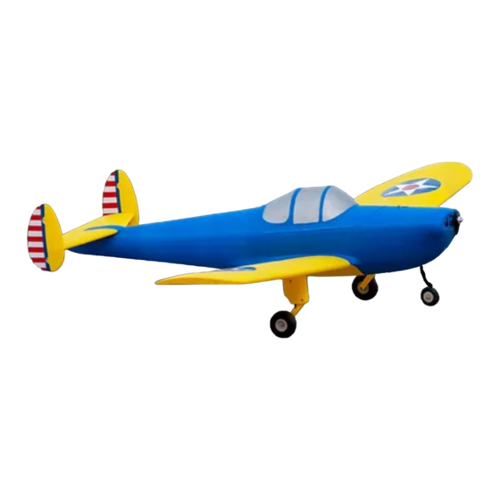
INTRODUCTION Thank you for purchasing a model by Lofted Aero! 3D printed aircraft are an exciting new segment of the hobby, and we’ve got no shortage of ideas for new designs. Your support helps us make those reality. The ERCO Ercoupe is a general aviation aircraft from a time when flying was immensely popular. - Page 3 M2 x 20 (x2) Shock Absorber Upper Mount Nuts M2 Locking (x2) Shock Absorber Lower Mount Nuts M2.5 Locking (x2) A hardware pack containing all screws, nuts, and washers will be available from Lofted Aero in January 2019. P a g e...
- Page 4 200mm x 200mm x 150mm print volume (or greater) If your printer setup is different, Lofted Aero recommends using the Simplify3D slicer and the provided factory files. Simplify3D includes many features ideal for thin-wall printing, including allowing multiple processes per print, control over the layer start location, and good control of retraction settings.
-
Page 5: Print Log
PRINT LOG You can print and use this table to keep track of printing progress, time, and weights. WING Part Weight (intended) Weight (actual) Print time Wing LR1A (27g each) Wing LR1B (34g each) Wing LR2A (24g each) Wing LR2B (24g each) Wing LR3 (44g each) -
Page 6: Landing Gear
TAIL Part Weight (intended) Weight (actual) Print time Horizontal Tails (20g per side) Elevators (13g per side) Vertical Tails (9g per side) Rudders (10g per side) LANDING GEAR Part Weight (intended) Weight (actual) Print time Nose Gear Insert Main Landing Gear (31g per side) Wheel Hubs 24g total... - Page 7 JOINING PARTS The Ercoupe’s printed sections are joined together with CA glue (Bob Smith brand works well) and activator. There are a few different types of joints throughout the model. BASE-TO-TOP JOINT This is the most common type of joint, where the base of one part is glued to the top of another part.
-
Page 8: Wing Assembly
WING ASSEMBLY 1. Assemble the ailerons. Start by joining section 1 to section 2 and section 3 to section 4 separately. Then, glue both subassemblies together at the control horn in the middle. 2. Assemble sections 1A and 2A, then sections 1B and 2B. P a g e... - Page 9 3. Spread glue liberally along the joining faces between the assembled “A” and “B” subassemblies. Join them together, standing the root ends on a flat surface to help maintain alignment. Use CA activator to secure. 4. Complete the wing panels by gluing sections 3, 4, 5, and 6 in sequential order. P a g e...
- Page 10 5. Place a drop of glue on each hinge pin, then push them into their mount holes in the wings. Be sure that their rotation axes are aligned with the aileron’s hingeline. Then, use activator to secure. 6. Place a drop of glue on the exposed ends of all three hinge pins and carefully install the aileron, making sure the hinge pins engage their mount holes.
- Page 11 7. Install 300mm (12”) servo extensions on the aileron servos and thread the leads through the tubes in the wing. 8. Center the aileron servos with a servo tester or receiver, then install the control arms. 9. Using servo tape, E6000 glue, or low-temp hot glue, secure the aileron servos in their pockets. If not using EZ-Connectors, it may help to wait to glue until after installing the pushrods.
- Page 12 11. Spread glue liberally on one wing root, then join the two completed wings together. 11 | P a g e...
-
Page 13: Fuselage Assembly
FUSELAGE ASSEMBLY 1. Install a pen spring on the end of the hatch latch, then slide it into fuselage section 2. Then join sections 2 and 3 with CA, making sure the hatch latch slides freely. 2. Join section 4 to section 3, applying the CA to section 4 to avoid getting glue on parts of the wing saddle that aren’t involved in the joint. - Page 14 3. Join section 5 to section 4. Then join section 5 to section 6, applying the CA to section 5 to avoid getting glue on parts of the wing saddle that aren’t involved in the joint. 4. Complete the fuselage by joining sections 7 and 8 to the assembly. Do not attach sections 1 or 9 at this time –...
- Page 15 6. Center the elevator servo with a servo tester or receiver, then thread lead through its guide tube. Using E6000 glue or low-temp hot glue, secure the elevator servo in its pocket in the fuselage. 7. Make a z-bend on one end of a long pushrod and install it in the elevator servo arm. Feed the pushrod through the guide tube in the fuselage, then secure the servo arm on the servo.
-
Page 16: Tail Assembly
TAIL ASSEMBLY 1. Join horizontal tail sections 1 and 2 on each side. 2. Join the rudder sections and vertical tail sections. 15 | P a g e... - Page 17 3. Place a drop of glue on each hinge pin, then push them into their mount holes in the vertical tails. Be sure that their rotation axes are aligned with the rudder’s hingeline. Then, use activator to secure. 4. Place a drop of glue on the exposed ends of all hinge pins and carefully install the rudders, making sure the hinge pins engage their mount holes.
- Page 18 5. Install EZ-Connectors on the rudder control horns as shown. Remove the tabs from the rudder servos. 6. Install 600mm (24”) servo extensions on the rudder servos and thread the leads through the tubes in the horizontal tails. Soldering is recommended to avoid the bulk of servo connectors. 7.
- Page 19 8. Spread glue liberally on the end of the horizontal tail halves. Set the vertical tail & rudder assemblies in place while sliding the rudder pushrods through the EZ-Connectors on the rudders. When satisfied with alignment, use CA activator to secure. Center the rudders and tighten the EZ-Connectors. 9.
- Page 20 10. Assemble the elevator by first joining sections 1 and 2 on each side, then joining both halves in the center at the control horn. 11. Place a drop of glue on four hinge pins, then push them into their mount holes in the horizontal tails. Be sure that their rotation axes are aligned with the elevator’s hingeline.
- Page 21 12. Dry-fit the elevator onto the hinge pins and center it, then mark the location of the elevator control horn on the pushrod. Make a z-bend at this location. 13. Fit the z-bend into the elevator control horn. Then place a drop of glue on the exposed ends of all hinge pins and carefully install the elevator, making sure the hinge pins engage their mount holes.
-
Page 22: Nose Gear Assembly
NOSE GEAR ASSEMBLY 1. Glue the nose wheel hub halves together inside the nose tire. 2. Use a bench vice and a hammer to bend the nose gear rod to conform to the shape of the printed template. Cut the excess with a hacksaw or rotary tool. 21 | P a g e... - Page 23 3. Press a shaft collar into the nose steering arm, making sure to align the set screw holes. 4. Slide the nose shaft through the steering arm and printed nose gear mount insert, then secure by tightening the shaft collar inside the steering arm and another shaft collar on the end. Using thread locker is recommended.
- Page 24 5. Spread CA on the sides of the nose gear mount insert, then press it into place in the fuselage. Spray activator to secure. 6. Thread the nose steering servo lead through the tube in the fuselage, using an extension if necessary. Fix the servo in place with E6000 glue or low-temp hot glue.
- Page 25 7. Make a nose steering pushrod with a z-bend on each end. Center the nose steering servo with a servo tester or receiver, then install the pushrod and control arm. 8. Using two shaft collars, install the nose wheel as shown. 9.
-
Page 26: Main Gear Assembly
MAIN GEAR ASSEMBLY 1. Glue the main wheel hub halves together inside the tires. 2. Adjust the shock absorber springs to their stiffest position. Install a short ball link in each end. 3. Align the top end of the shock absorber (the ball link you just installed) with its mount hole in the gear pylon. - Page 27 4. Install the strut with an M3 x 22mm bolt and an M3 lock nut. The strut should be slop free but able to pivot with little resistance. 5. Attach the lower end of the shock absorber to the strut with an M2.5 x 10 bolt and an M2.5 lock nut. 6.
- Page 28 7. Attach the pylons to the wing with M4 x 14 self-tapping screws. Liberally apply CA to the joint as well. 27 | P a g e...
-
Page 29: Power System Installation
POWER SYSTEM INSTALLATION 1. Install the cross mount on the motor – use thread locker. Then connect the motor and ESC with bullet connectors or direct solder joints. Verify proper direction. 2. Lower the ESC and wiring into the fuselage from the front. Then, use four self-tapping screws to attach the cross mount to the fuselage. - Page 30 3. Install the prop adapter. Then join fuselage section 1 to section 2, ensuring that the center hole is aligned with the motor shaft. 4. Use double-sided tape or Velcro to fix the ESC to the inside of the fuselage. NOTE: Should you wish to install a front-mounted motor, an alternate Fuselage 1 is included.
-
Page 31: Final Assembly
FINAL ASSEMBLY 1. Fit the wing into place, threading the aileron servo leads through the tubes in the wing saddle. 2. Spread CA on the body of each wing nut holder, then drop them into their pockets in the fuselage. 3. - Page 32 ELECTRONICS SETUP & FINISHING 1. Connect the ESC and all servos to the receiver. If your ESC does not have a switching regulator, it is recommended to use a separate BEC to power the servos and receiver. If possible, each aileron should have its own channel to enable independent end points and differential.
- Page 33 3. With the propeller and canopy fitted, position the battery such that the aircraft balances on the CG marks on the underside of the wing. Secure with adhesive Velcro and/or Velcro straps. 4. Apply graphics if desired. You’re ready to fly! NOTE: Since the Ercoupe was designed to be easy to fly, most had no rudder pedals.
- Page 34 CONTACT US Have a question, issue, or just a cool idea for the next aircraft we should model? Drop us an email at: info@loftedaero.com 33 | P a g e...
Need help?
Do you have a question about the ERCO ERCOUPE and is the answer not in the manual?
Questions and answers