Table of Contents
Advertisement
Advertisement
Table of Contents

Subscribe to Our Youtube Channel
Summary of Contents for Stihl USG
-
Page 2: Table Of Contents
Guide to Using this Manual ....2 Safety Precautions ......3 Thank you for choosing a quality Applications ........4 engineered STIHL product. Mounting the Tool ......4 This machine has been built using Selecting the Grinding Wheel ... 6 modern production techniques and Mounting the Grinding Wheel ... -
Page 3: Guide To Using This Manual
Engineering improvements in different ways: components. STIHL’s philosophy is to continually Step or procedure without direct Note or hint which is not essential improve all of its products. As a result, reference to an illustration. -
Page 4: Safety Precautions
STIHL or expressly approved by slip gloves, preferably observed when operating STIHL for use with your specific model. made of leather. the universal sharpener. Do not use any other grinding wheels since they will increase the risk of injury. -
Page 5: Applications
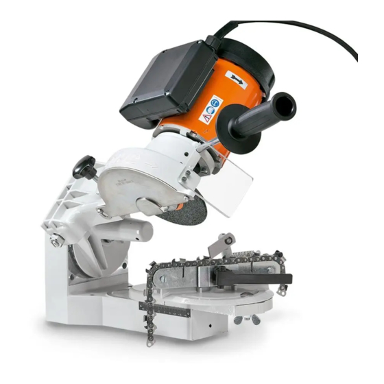
English Applications Mounting the Tool The STIHL USG sharpens all STIHL The unit may be mounted on a wall or Oilomatic saw chains, hedge trimmer workbench. blades and circular saw blades. If you mount the unit on a bench, note... - Page 6 English Loosen the M5x10 screws (1) Screw the short thread of M10x145 and then lift and remove the guard stud (7) into the housing bore (8). plate (2). Screw the M10 nut (9) onto the stud as far as stop. Fit motor (3) on motor arm (4).
-
Page 7: Selecting The Grinding Wheel
English Selecting the Grinding Wheel A = Grinding wheel 5203 750 7010 (2.4 mm radius at one side) B = Grinding wheel 5203 750 7013 (2.0 mm radius at one side) C = Grinding wheel 5203 750 7015 D = Diamond grinding wheel 5203 757 0901 Grinding Application... -
Page 8: Mounting The Grinding Wheel
English Mounting the Grinding Wheel Always check condition of grinding wheels by performing ringing test before mounting. Never use damaged grinding wheels. Loosen the M5x10 screws (1), then lift and remove the guard plate (2). Fit the O-ring (3) in the groove in the Grinding Installed position spacer (4) and then push the spacer... -
Page 9: Test Run
English Test Run Dressing the Scales Grinding Wheel Every time you mount a grinding wheel: Cordon off the general work area (danger zone). Run grinding wheel at maximum permissible speed for at least one minute. The profile of the grinding wheel is Scale A subject to wear. -
Page 10: Setup For Sharpening Saw Chain
English Setup for Sharpening Saw Chain Inspect the chain. Replace damaged or worn parts of the chain. Grind the new parts back to the shape and size of the other parts. Select the grinding wheel – see instruction sheet 0457 716 0000. Mount the grinding wheel –... - Page 11 English Determining Drive Link Gauge The clamp must be adjusted to suit the drive link gauge. Drive link gauge: Use slide caliper to measure dimension "a" note the digit (arrow) Adjusting the Clamp Take out the screws (3). Digit Drive link gauge in mm Take out the screws (4).
- Page 12 English Chain with 1.1/1.3 mm drive link Chain with 1.5/1.6 mm drive link Chain with 2.0 mm drive link gauge gauge gauge Fit the shim (5). Remove the shim (5) (if fitted). Remove the shim (5) (if fitted). Fit the screws (3). Fit the screws (3).
- Page 13 English Fit the clamping lever. Finding the Master Cutter Fitting the Saw Chain The shortest cutter is used as the master Release the clamping lever (1). cutter. Place the chain in position, drive link tangs (2) between the rails (3) – The master cutter is sharpened first.
- Page 14 English Setting the scales Set the scales to the values specified in the instruction sheet 0457 716 0000. Pull the master cutter back against The pivot pin (5) moves backward the stop (4). and forward so that the stop can be properly located against the back of the cutter.
- Page 15 English Adjusting Lateral Stop Move the stop (2) with the adjusting Tighten down the knurled nut on the screw (3) so that the master cutter's adjusting screw. Back off the travel limiting screw (1). side plate butts against the grinding Use the handle to bring the grinding wheel.
-
Page 16: Sharpening Procedure
English Sharpening Procedure Wear safety glasses. Sharpening the Master Cutter Switch on the motor. Bring motor arm slowly downward. Check sharpening process. Do not remove too much material. If necessary, switch off motor and readjust. Sharpen the side plate by applying the wheel several times –... - Page 17 English Check angle with a filing gauge. If side plate angle is too obtuse (wide): Use travel limiting screw to set motor arm lower. Avoid touching the drive links or tie straps with the grinding wheel. This could cause the chain to break. The travel limiting screw must now butt Sharpening Row of Cutters against the stop lug and the side plate...
-
Page 18: Lowering Depth Gauges
English Lowering Depth Gauges Sharpening the Second Row of Checking Depth Gauge Setting Cutters Select the filing gauge (special accessory) that matches the chain Set scale B to the same sharpening pitch. angle on the other side of the chain. Set scale C to the specified angle on the other side of the chain. - Page 19 English If the depth gauges have to be lowered: Select the correct grinding wheel – see instruction sheet 0457 716 0000 Mount the grinding wheel – see "Mounting the Grinding Wheel". Test run the grinding wheel – see "Test Run". Check profile of grinding wheel and dress if necessary –...
-
Page 20: Setup For Sharpening Hedge Trimmer Blades
English Setup for Sharpening Hedge Trimmer Blades Select the correct grinding wheel – see "Selecting Grinding Wheel". Mount the grinding wheel – see "Mounting the Grinding Wheel". Test run the grinding wheel – see "Test Run". Check profile of grinding wheel and dress if necessary –... - Page 21 English Setting the Scales HL 45, HL 75, HLR 85, HS 61 HS 75, 80, 85 HL 100, HS 246 HS 45 Scale A - 10° - 6° Scale B Mounting the Attachment for Scale C Principle of Clamp + 45° + 55°...
- Page 22 English Fitting double-sided cutting blade Fit the cutting blade (4) in position so that the cutting edges point to the rear. Fitting Cutting Blade Fitting one-sided cutting blade Turn the star knob (1) until the Fit the angle iron rail (5). spring (2) is in the positon shown.
- Page 23 English Adjusting the Stop Swing the motor arm up again. Swing the stop (4) into position by hand. Turn the star knob (1) clockwise Adjusting the lateral stop until the spring is in the position Turn the adjusting screw (5) until the Swing the motor arm down until the shown –...
- Page 24 English If stop is now correctly positioned: Adjusting sharpening depth Screw the travel limiting screw (1) Continue turning the star knob (3) down as far as the stop lug (2). Swing the motor arm down until the clockwise until the stop swings Tighten down the knurled nut (3) grinding wheel touches the gullet of back.
-
Page 25: Sharpening Hedge Trimmer Blades
English Sharpening Hedge Trimmer Blades Wear safety glasses to protect your eyes. Observe the following points when sharpening: The cutting blade must be correctly clamped in position and the stop must swing back out of the way. Bring the motor arm slowly downward. - Page 26 English 180° 180° Sharpening Double-Sided Hedge Take the cutting blade out of the Take the cutting blade out of the Trimmer Blades clamp and turn it 180° lengthwise – clamp and turn it over (180°) – cutting edges point to the rear. cutting edges point forwards.
- Page 27 English 180° 180° Take the cutting blade out of the clamp and turn it over (180°) – cutting edges point forwards. Set scale C to opposite angle. Sharpen the teeth. Take the cutting blade out of the Sharpening One-Sided Hedge clamp and turn it 180°...
-
Page 28: Preparations For Sharpening Circular Saw Blade
English Preparations for Sharpening Circular Saw Blade Check the blade. Always perfom a ringing test. Do not continue to use warped or cracked blades since they may shatter. Select the correct grinding wheel – see "Selecting the Grinding Wheel". Mount the grinding wheel – see "Mounting the Grinding Wheel". - Page 29 English Position the saw blade (2) on the There are saw blades with shoulder stud (1) so that the cutting square ground teeth (5) edges point to the left (counter- (scale C = 0) and clockwise). Fit the locator (4) over the shoulder bevel ground teeth (6) stud and push it home –...
- Page 30 English Set angles as specified in the Adjusting the Stop following table. Adjusting the lateral stop Swing the motor arm down. Type of tooth Scale Scale Use the adjusting screw (1) to move the stop (2) so that the side plate of Chisel tooth, the tooth to be sharpened butts standard...
- Page 31 English Sharpening Limits Chisel tooth: – Sharpening depth: max. 5 mm – Top plate must not be sharpened back to more than half its length. – Tooth set must not be less than 1 mm. Checking Tooth Set Scratcher tooth After sharpening chisel tooth saw –...
-
Page 32: Sharpening Circular Saw Blade
English Sharpening Circular Saw Blade Sharpening Remaining Teeth The sharpening process now depends on how the teeth are ground. Saw blade without bevel ground teeth (scale C = 0°): Rotate the saw blade counter- clockwise to the next tooth. Sharpen all teeth with the same setting. -
Page 33: Maintenance Chart
English Maintenance Chart Please note that the following maintenance intervals apply for normal operating conditions. If your daily working time is longer than normal or conditions are difficult, shorten the specified intervals accordingly. Visual inspection condition) Complete machine Clean Check Machine mounting Retighten Check operation... -
Page 34: Minimize Wear And Avoid Damage
Clamping lever and thrust pad – Alterations or modifications to the – Damage to the unit due to neglect – Clamping and guide rails product not approved by STIHL. or deficient maintenance. – Stop – Using attachments or sharpening –... -
Page 35: Main Parts Of Sharpener
1 Star knob 2 Spring 3 Stop 4 Adjusting screw 5 Clamp 6 Angle iron rail USG with attachment for Attachment for Oilomatic saw chain circular saw blades 1 Motor 1 Locator 2 Switchbox 2 Shoulder stud... -
Page 36: Specifications
Attachment (tool rest) for circular saw parts. blades Saw set for checking and correcting tooth set Contact your STIHL dealer for the latest information on these and other special accessories. according to EN ISO 11204, measured at operator’s ear while... -
Page 37: Certificate Of Conformity
EN 61000-3-2, EN 61000-3-3 and An independent organization has EN 60204-1 certified that all products manufactured by STIHL meet the strict requirements of the ISO 9001 standard for quality management systems in terms of product development, materials purchasing, production, assembly,...
Need help?
Do you have a question about the USG and is the answer not in the manual?
Questions and answers