Table of Contents
Advertisement
Quick Links
Advertisement
Table of Contents

Subscribe to Our Youtube Channel
Summary of Contents for JAC JA95-060
- Page 1 JA95-060 Audio Controller Five Transceiver - Expander Installation and Operating Manual Rev A Jupiter Avionics Corporation 1959 Kirschner Road Kelowna BC Canada V1Y 4N7 Tel: +1 778 478 2232 Toll-Free: 1 855 478 2232 www.jupiteravionics.com Rev B Page i...
- Page 2 All rights reserved Jupiter Avionics Corporation (JAC) permits a single copy of this manual to be printed or downloaded for the express use of an installing agency. Any such electronic or printed copy of this manual must contain the complete text of this copyright notice.
-
Page 3: Table Of Contents
JA95-060 Audio Controller - Five Transceiver - Expander Installation and Operating Manual Table of Contents SECTION 1 - DESCRIPTION ..............................1 System Overview ..............................1 Features Overview ..............................1 Inputs and Outputs ..............................1 1.3.1 Inputs ................................1 1.3.2 Outputs ................................1 Specifications ................................ - Page 4 JA95-060 Audio Controller - Five Transceiver - Expander Installation and Operating Manual Appendix A - Installation Drawings ........................... A1 Introduction ................................A1 Installation Drawings ............................. A1 Appendix B - Certification Documents ..........................B1 Airworthiness Approval ............................B2 Instructions for Continued Airworthiness ......................B2 Environmental Qualification Form .........................
-
Page 5: Section 1 - Description
The JA95-060 Audio Controller - Five Transceiver - Expander is a compact, lightweight panel that allows connection of up to 4 additional radios to the aircraft audio system. The JA95-060 is compatible with the transceiver connections of any of Jupiter’s JA9x series of audio controllers as well as any civil aviation audio controller. -
Page 6: Specifications
A95-060 Au dio Control ller - Five T Transceiver - Expande Installation and Opera ting Manua Specific cations 1.4.1 Electrica l Specificat tions Power Input Primary no ominal voltage 28 Vdc Secondary y nominal volt tage 14 Vdc Maximum voltage 32.2 Vdc Minimum v voltage... -
Page 7: Mechanical Specifications
Bonding 2.5 m Installation n kit part num INST-JA9 1.4.3 Configur ation Conn ector The JA95-060 0 configuratio n connector c communicatio on standard fo or CONFIG D DATA TO JA9 95 data input s signal and CONFIG DAT... -
Page 8: Product Configuration Software Version
JA95-060 Audio Controller - Five Transceiver - Expander Installation and Operating Manual 1.4.4 Product Configuration Software Version Configuration of the JA95-060 requires the Product Configuration Software (ProCS) version v0.61.0 or later. Refer to the release notes from http://www.jupiteravionics.com/productsoftware.php or contact Jupiter Avionics to ensure the correct version is used. -
Page 9: Section 2 - Installation
JAC dealer or agency. This warranty covers the cost of all materials and labour to repair or replace the unit, but does not include the cost of transporting the defective unit to and from JAC or its designated warranty repair centre, or of removing and replacing the defective unit in the aircraft. -
Page 10: Mechanical Installation
2.4.3 Mechanical Installation The JA95-060 can be mounted in any attitude and location with adequate space for the front panel and sufficient clearance for the connector and wiring harness. It requires no direct cooling. 2.4.4 Legend Replacement The JA95-060 illuminated legends are field replaceable. -
Page 11: Configuration Cabling Requirements
USB A Male to RS232 3.5mm Plug CAB-USB-0006 2.5.2 ProCS™ Setup The ProCS™ JA95-060 menu item 'ProCS Setup' provides Setup drawings showing the cabling arrangement for connecting the JA95-060 to a computer running the ProCS™. 2.5.3 Configurable Settings A standard unit is shipped from the factory with all internal adjustments configured to the default levels. At installation, it may be desirable to change some of these settings to suit the local operating environment. - Page 12 JA95-060 Audio Controller - Five Transceiver - Expander Installation and Operating Manual Radios 2.5.3.2 The Radios window is used to define the radios for the transceivers. 2.5.3.3 Receive Levels The receive level of each of the RX inputs can be adjusted from 1 to 10 Vrms.
-
Page 13: Other Configuration Features
(Default +28 Vdc). 2.5.4 Other Configuration Features In the JA95-060 Product Information Window, the model number, serial number and check sum of the JA95-060 Audio Controller - Five Transceiver - Expander can be viewed. Installation Kit The kit required to install this unit is not included with the unit. -
Page 14: Installation Drawings
The interconnects and connector maps in Appendix A of this manual are generic drawings based on the standard version of the JA95-060. However, if a unit has been configured using JAC’s ProCS™ software to change switch legends or lighting voltages, the software can be used to generate fully customized interconnects and connector maps for use by the installer. -
Page 15: Section 3 - Operation
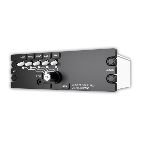
Jupiter’s JA9x series of audio controllers as well as any civil aviation audio controller. The text on the JA95-060 legend (shown here as AUX) should be selected to match the text on the main panel legend representing the expanded transceiver position. -
Page 16: Front Panel Controls
JA95-060 Audio Controller - Five Transceiver - Expander Installation and Operating Manual Front Panel Controls Note: The legends and deadfront annunciator are removable and may be replaced with custom ordered parts. The controls will be referred to by the default legend and annunciator names as shown below. -
Page 17: Transmit Annunciator - Tx
(AUX in these examples) is selected on the main audio panel. When the JA95-060 receives an incoming transmission on a transceiver or receiver that has been selected, either by the white transceiver receive switches (1) or the transmit selector (4), the incoming audio will be directed to the user’s phones. -
Page 18: Transmitting (Transmit Operation)
3.4.3 Transmitting (Transmit Operation) Note: Transmission on any of the transceivers linked to the JA95-060 is only possible if the designated transceiver (AUX in these examples) is selected on the main audio panel. To select a transceiver, rotate the Transmit Select Switch until it aligns with the line leading to the Transceiver Select switch legend (see 1) - default legends AUX1, AUX2, AUX3, AUX4, or AUX5. -
Page 19: Appendix A - Installation Drawings
Appendix A - Installation Drawings Introduction The drawings necessary for installation and troubleshooting of the JA95-060 Audio Controller - Five Transceiver - Expander are in this Appendix, as listed below. Note: A fully customized set of Connector Maps and Interconnects can be created using the ProCS software. - Page 20 Audio Controller - Five Transceiver - Expander P1 Connector Map JA95-060 JA95-060 Connector Map Rev A RECEIVE CONNECTOR 10 11 12 13 14 15 16 17 18 19 37 PIN FEMALE DMIN MATING CONNECTOR 20 21 22 23 24 25 26 27 28 29 30 31 32 33 34 35...
- Page 21 Audio Controller - Five Transceiver - Expander P2 Connector Map JA95-060 JA95-060 Connector Map Rev A TRANSMIT CONNECTOR 50 PIN FEMALE DMIN 10 11 12 13 14 15 16 17 MATING CONNECTOR 18 19 20 21 22 23 24 25 26 27 28 29 30 31 32 33...
- Page 22 CONFIG DATA FROM JA95 GROUND MODE SELECT Audio Controller - Five Transceiver - Expander P3 Connector Map JA95-060 JA95-060 Connector Map Rev A FRONT PANEL CONFIGURATION CONNECTOR ACCEPTS THE FOLLOWING PLUG FORMATS MATING PLUG NAMES UNIT SIGNAL NAMES TIP: TX DATA...
- Page 23 Audio Controller - Five Transceiver - Expander P4 Connector Map JA95-060 JA95-060 Connector Map Rev A CHASSIS GROUND CONNECTOR CHASSIS GROUND CONNECTOR #4 RING TERMINAL MATING CONECTOR PREPARED 12-03-18 CHECKED TITLE 12-03-18 APPROVED NCAGE CODE PART NO. SHEET L00N3 DOC NO.
- Page 24 CONNECTION TO AIRFRAME GROUND SHOULD BE MADE WITH 20 AWG WIRE. LENGTH NOT TO EXCEED 3 FT (0.9 M). CABLE SHIELDS AT THE JA95-060 CONNECTOR PINS SHOULD BE TERMINATED TO AIRFRAME GROUND USING A TAG RING P/N: MS27741-5 OR EQUIVALENT.
- Page 25 + 5 VDC LIGHTS PREPARED 11-14-18 CHECKED TITLE Audio Controller - Five Transceiver - Expander J1 Interconnect 11-14-18 APPROVED NCAGE CODE PART NO. SHEET L00N3 JA95-060 DOC NO. JA95-060 Interconnect Rev A.dwg JUPITER AVIONICS TEMPLATE AUTOCAD PORTRAIT SIZEA REV B.DWT...
- Page 26 SPARE 29 SPARE 30 PREPARED 11-14-18 CHECKED TITLE Audio Controller - Five Transceiver - Expander J2 Interconnect 11-14-18 APPROVED NCAGE CODE PART NO. SHEET L00N3 JA95-060 DOC NO. JA95-060 Interconnect Rev A.dwg JUPITER AVIONICS TEMPLATE AUTOCAD PORTRAIT SIZEA REV B.DWT...
- Page 27 OPTION: PROGRAMMING FROM JA99-001 4 POLE MALE 3.5MM STEREO JA95-060 FRONT PANEL CONFIGURATION INPUT MATING CONNECTOR MODE SELECT/CONFIG AUDIO 3RD RING CONFIG DATA TO JA95 PART OF JA99-001 CONFIG DATA FROM JA95 CONFIGURATION CABLE 1ST RING GROUND 2ND RING MODE SELECT/CONFIG AUDIO...
- Page 28 ANGLES: 0.5 DEG SHEET 12-03-18 NCAGE CODE PART NO. APPROVED L00N3 JA95-060 CONFIDENTIAL & PROPRIETARY DOC. NO. MATERIAL: TO JUPITER AVIONICS CORP. JA95-060 Mechanical Installation Rev A.SLDDRW FINISH: DRAWING NOT TO SCALE JUPITER AVIONICS TEMPLATE SOLIDWORKS PORTRAIT SIZEA REVB .DRWDOT...
- Page 29 AUDIO PANEL PREPARED 12-10-18 CHECKED TITLE Audio Controller - Five Transceiver - Expander Equipment Block Diagram 12-10-18 APPROVED NCAGE CODE PART NO. SHEET L00N3 JA95-060 DOC NO. JA95-060 Equipment Block Diagram Rev A.dwg JUPITER AVIONICS TEMPLATE AUTOCAD LANDSCAPE SIZEA REV B.DWT...
- Page 30 Legend Removal Caution: Take care not to scratch or otherwise damage the faceplate or the legend. To facilitate legend removal, JAC provides a legend extractor tool - part # Figure 1 TOL-CUST-EXTR (figure 1) that fits into the recesses on the legend.
-
Page 31: Appendix B - Certification Documents
JA95-060 Audio Controller - Five Transceiver - Expander Installation and Operating Manual Appendix B - Certification Documents Rev A Page B1... -
Page 32: B1 Airworthiness Approval
The JA95-060 Installation Manual provides detailed installation instructions and wiring diagrams (Section 2, and Appendices A and B). Power is supplied to the JA95-060 through an existing [ ]-Amp circuit breaker that was previously used by the original audio panel. The net electrical load is unchanged. -
Page 33: B3 Environmental Qualification Form
Refer to the JA95-060 Maintenance Manual. 7. Removal and Replacement Information Refer to Section 2 of this manual - the JA95-060 Installation and Operating Manual. If the unit is removed and reinstalled, a functional check of the equipment should be conducted. - Page 34 JA95-060 Build Configuration Rev A Manufacturer’s Test Report: JA95-001 Test Report (Qualification - Final) Rev B JA95-060 Test Report (Environmental - Vibration - 20181204) Rev A JA95-060Test Report (Environmental - Operational Shock & Crash Safety - 20181206) Rev A JA95-060 CAN-TSO Design Change Assessment Rev A Manufacturer’s Specification...
- Page 35 JA95-060 Audio Controller - Five Transceiver - Expander Environmental Qualification Form CONDITIONS SECTION DESCRIPTION OF TESTS CONDUCTED Operational Shock and Crash Safety Operational Shock 7.2.2 Equipment tested to Category B (6 g for 11 ms) Crash Safety (impulse) 7.3.2 Equipment tested to Category B (20 g for 11 ms) Crash Safety (sustained) 7.3.3...
- Page 36 Other Tests REMARKS This product is a derivative of the JA95-001. All tests were performed on a JA95-001 and JA95-060. A similarity analysis between the two products is detailed in the Jupiter Avionics Corp. document: JA95-060 CAN-TSO Design Change Assessment Rev A During exposure to vibration test conditions the following critical resonances changed frequency greater than 1.5%:...
Need help?
Do you have a question about the JA95-060 and is the answer not in the manual?
Questions and answers