Inficon RC1000 Series Operating Instruction
Remote control for leak test equipment
Hide thumbs
Also See for RC1000 Series:

Related Manuals for Inficon RC1000 Series

Summary of Contents for Inficon RC1000 Series
- Page 1 O P E R A T I N G I N S T R U C T I O N lina15en1-05-(1806) Catalog No.: 551-010 551-015 from software version V1.5 RC1000 Remote control for leak test equipment...
- Page 2 Imprint INFICON GmbH Bonner Straße 498 50968 Köln Germany © Copyright 2018 INFICON GmbH, Cologne. This document may not be reproduced in any form without the permission of INFICON GmbH, Cologne.
-
Page 3: Table Of Contents
Content Operating instructions How to use this manual Warning and danger symbols Glossary Important safety instructions Intended use User requirements Restrictions of use Hazards in the event of intended use Description of the RC1000 Operating Elements Back of the RC1000 Supplied equipment Installation Connection to the leak detector... - Page 4 5.3.8.2 Energy-saving options (RC1000WL) 5.3.8.3 Set Time and Date Operating the leak detector Paging function Maintenance tasks Spare parts Maintenance Cleaning Transport and disposal Transporting Disposal Technical Data Weight / dimensions Characteristics Environmental Conditions Mains power for wall plug-in power supply Wireless permits of RC1000WL Ordering information Declaration of conformity...
-
Page 5: Operating Instructions
Operating instructions How to use this manual • Please read this manual before commissioning the wireless RC1000WL or the wire-bound RC1000C remote control. • Keep the manual so that you can use it any time. • Enclose the operating manual if the device is ever passed on to third parties. -
Page 6: Glossary
Glossary Menu The menu enables the operator of the RC1000WL or RC1000C remote control to program the remote control to reflect their personal preferences. The menu has a tree structure. "As delivered" status The condition of the RC1000WL or RC1000C remote control as it left the factory. -
Page 7: Important Safety Instructions
RC1000. The RC1000 remote control must only be used for the purpose and within the context outlined in this manual. Use only INFICON accessories. User requirements Skilled personnel The RC1000 remote control must only be connected and operated by properly trained staff. -
Page 8: Restrictions Of Use
Restrictions of use Danger in explosive environments. The RC1000C / RC1000WL remote control may only be used away from explosive environments. Hazards in the event of intended use Possible interference with pacemakers. The performance of pacemakers may be affected by the magnets on the back of the RC1000C / RC1000WL remote control. - Page 9 Possible radiation hazard. When the device is operated, a minimum distance of 7 cm between the remote control and people must be observed, with the exception of hands and wrists. Operation at a shorter distance than indicated above is not allowed.
- Page 10 Possible risk of destruction. The RC1000 remote control may be damaged beyond repair by penetrating liquid. Do not switch on the RC1000 remote control if liquid has penetrated the unit. Contact the INFICON Service Department. Important safety instructions...
- Page 11 (see Technical specifications chapter 8). If the RC1000 remote control has been stored under such conditions, leave it switched off and contact the INFICON Service Department. Possible risk of damage.
- Page 12 Any changes made to the RC1000 remote control by the user may result in a violation of statutory provisions or may affect the EMC properties and safety of the product. INFICON does not accept any liability for the consequences of such changes. Important safety instructions...
-
Page 13: Description Of The Rc1000
Description of the RC1000 The RC1000 remote control has been designed to operate the selected INFICON leak detectors. The RC1000 remote control is accommodated in a robust housing the shape of which enables ergonomic working. Magnets on the underside of the unit enable it to be attached to horizontal or vertical metal surfaces. -
Page 14: Operating Elements
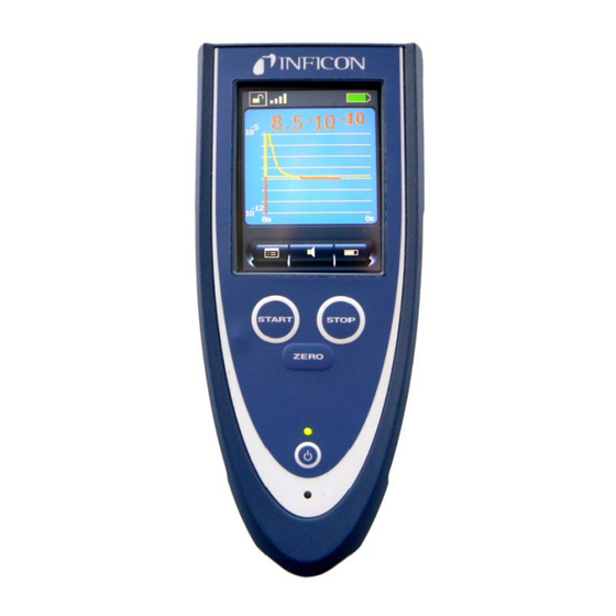
Operating Elements Pos. Description START button ZERO button POWER button Touch Display STOP button Operating LED Charge LED Fig. 1 RC1000 remote control POWER button RC1000WL: Power switch. After pressing and briefly holding the switch, the operating LED lights up as confirmation and flashes when the remote control is ready for use. - Page 15 START button (See 5.4). Starts the leak test of the leak detector (See the Technical Manual of the leak detector, and observe the menu option "Control location"). STOP button Ends leak testing (See 5.4). ZERO button (See 5.4). Activates the ZERO function Touch Display Shows measurements displayed numerically or as a curve, indicates statuses and offers operating interfaces.
-
Page 16: Back Of The Rc1000
Back of the RC1000 Pos. Description Magnets for attaching the unit to metal surfaces, e.g. to the leak detector. M3 threaded bushings to attach holders Risk of damage. Use screws that reach max. 6 mm into the housing. Sound outlet aperture for the integrated loudspeaker. -
Page 17: Supplied Equipment
Supplied equipment Cat.-No. 551-015 Remote control RC1000WL, wireless Supplied Remote control RC1000WL equipment: Connection cable, 4 m Wall plug-in power supply (for integrated battery) Radio transmitter Connection cable for radio transmitter Operating instructions Cat.-No. 551-010 Remote control RC1000C, non-wireless Supplied Remote control RC1000C equipment: Connection cable, 4 m... -
Page 18: Installation
Installation Connection to the leak detector RC1000WL (wireless) The RC1000WL remote control is connected to the leak detector by means of a wireless data connection. Connect the leak detector to the radio transmitter for this purpose (see chapter 4.2). The RC1000WL remote control is shipped set-up for connec- tion with the supplied radio transmitter. -
Page 19: Connecting Radio Transmitter And Leak Detector
Connecting radio transmitter and leak detector Connecting the radio transmitter for the RC1000WL (wireless) remote control: Use Velcro to position the radio transmitter (1) in a suitable location on the SmartTest leak detector so that there is a direct line of sight between the antenna and the remote control. -
Page 20: Inputs And Outputs
Inputs and outputs The inputs and outputs of the RC1000 remote control have covers to prevent large dirt particles and moisture from pen- etrating. Notice: The IP42 safety class can only be guaranteed if the covers are closed. RJ25 socket The RJ25 socket is located at the underside of the RC1000 remote control and closed with a protective plug when delivered. - Page 21 Connections on the side Notice: Fold the protective strip upwards before connecting a plug. Fig. 5 Connections on the side (without cover) Pos. Description USB connection Insert the USB stick (FAT formatted) to record data. 3.5 mm jack for stereo headphones Standard stereo headphones with a 3.5 mm jack plug and >2x32 Ohm impedance can be connected to the jack.
-
Page 22: Wall Plug-In Power Supply
Wall plug-in power supply Possible risk of voltage hazard. Do not open the external power supply of the RC1000WL remote control. This might result in electric shock and/or injuries. Risk due to incorrect power supply unit. Using an external power supply which has not been approved by the manufacturer of the remote control may result in electric shock, damage and/or injuries. - Page 23 Connect the plug of the power supply with the socket of the (see Fig. 5, Pos. 3), to charge the integrated RC1000WL battery. The RC1000WL is always switched on while the power supply cable is connected and the battery is being charged, the Charging LED is lit.
-
Page 24: Operating The Remote Control
Operating the remote control RC1000 Starting up the After starting up, a start screen with a „Welcome“ message is shown on the touch display. Fig. 7 Touch-Display of the RC1000 The RC1000WL remote control searches for a receiver (radio transmitter) of a leak detector after starting up to connect with If no devices with which a connection is possible were found in the area, a message „no data connection“... -
Page 25: Touch Display Operation
Touch display operation Fig. 8 Symbols and information on the display Pos. Description Pos. Description Lock/unlock buttons Display of measured values Wireless connection Status bar Data set of the entry Menu (access to the main menu) Charging status display Sound volume Trigger level 10 Toggle display of measured values Operating the remote control... - Page 26 Display functions The touch display functions can be used by lightly touching the relevant symbol on the display with a finger or a blunt pen. • "Lock buttons": Touch and hold the symbol for more than 2 seconds to lock out touch display operation. The buttons then become dark.
-
Page 27: Main Menu For Configuration
Main menu for configuration The "Menu" symbol (Fig. 8 Pos. 8) can be used to access the main menu for the configuration of the remote control. The functions of the individual buttons are described in more detail in the following. Fig. -
Page 28: Buttons With Basic Functions
5.3.1 Buttons with basic functions Fig. 10 Buttons with basic functions If displayed, these buttons have the following functions: "?" opens a help window for the current display. • Click on "?". • Use the arrow keys to scroll through longer texts. •... -
Page 29: Connecting / Disconnecting (Rc1000Wl)
5.3.2 Connecting / disconnecting (RC1000WL) The RC1000WL remote control searches for a receiver (radio transmitter) of a leak detector after turning on or after pressing the "Connect" button. If no connection is found in the area within 20 seconds, the search is aborted. -
Page 30: Setting The Trigger Level
5.3.3 Setting the trigger level Setting the trigger level: The basic level and exponent of the trigger level of the remote control are set here. • The individual input fields can be selected with "<" and ">". • The selected field is marked red and can be changed. -
Page 31: Scale: Scaling Of The Leak-Rate Curve
5.3.4 Scale: scaling of the leak-rate curve Scaling options of the leak-rate curve and the bargraph: • Q(t) axis: Opens a submenu with a choice between linear and logarithmic display of the measured values and the automatically scaling (see Fig. 14). - Page 32 Scaling the time axis of the leak-rate curve: The selected value is displayed in the centre. The shown time in this menu is the displayed range of the time axis of the leak-rate curve. Fig. 15 Menu scaling of the time axis Operating the remote control...
-
Page 33: Sound Volume
5.3.5 Sound volume In this menu you can set the volume of the acoustic signals at the leak detector and at the remote control using the "Arrow up" and "Arrow down" buttons. Possible risk of hearing damage. The hearing may be damaged by the alarm signal. If a high volume is set, only briefly expose the hearing to the alarm signal or use ear protection. -
Page 34: Recorder
5.3.6 Recorder Recording measurements, copying or deleting recorded data • Select „Settings“ to start, to stop or to configure the recording of measurements. Opens a submenu (see Fig. 18). • Select „Copy“ to write recorded data to a plugged-in USB stick. Opens a submenu (see Fig. - Page 35 Notice: Set correct values of date and time (see 5.3.8.3) to identify the appropriate data files after recording. Recorded data files can be copied to a plugged-in USB stick • Plug-in the USB stick to the RC1000. • Select the files by clicking on it or use the „Select all“...
-
Page 36: Info: Device Information
5.3.7 Info: device information "Info" provides among others information about the power level of the battery, the wireless connection, and gives information on the current version on 5 information pages. Detailed information: • Select the desired information with the arrow keys. •... -
Page 37: Miscellaneous
5.3.8 Miscellaneous In the "Miscellaneous" menu, you can set the language, make software updates, set the time and the date, and select energy-saving options. The menu point Service offers expanded functions and test options via an access PIN. Fig. 22 Miscellaneous menu, submenu Language 5.3.8.1 Language selection: •... -
Page 38: Energy-Saving Options (Rc1000Wl)
5.3.8.2 Energy-saving options (RC1000WL) The background illumination can be automatically decreased after a time between 15 s and 10 min. This lowers the energy consumption and the operating time of the battery is extended. • Set the time period with "Arrow up" and "Arrow down". -
Page 39: Set Time And Date
5.3.8.3 Set Time and Date Setting the time: • The fields can be selected individually with "<" and ">". • The field selected for change is marked red. • Make changes via the numeric keypad. • After changing a digit, the red mark automatically changes to the next field. -
Page 40: Operating The Leak Detector
Operating the leak detector The "START/STOP" and "ZERO" buttons on the remote control can be used to operate the leak detector in the same manner as on the actual leak detector. Notice: You must observe the operating instructions of the leak detector in any case! If the remote control displays a menu page of the configura- tion, you can change to the status display of the leak detector... - Page 41 After starting up, the leak test device can be in „Evacuating“ or „Measure“ mode: Fig. 26 „Evacuating“ and „Measure“ status displays (numerical and bar graph) Fig. 27 „Measure“ (curve) and „Vented“ status displays STOP button Pressing the STOP button interrupts the measurements. The inlet is vented if the button is pressed and held.
-
Page 42: Paging Function
ZERO button Pressing the ZERO button activates the background suppression in the leak detector. (See the operating instructions of the leak detector.) Notice: The „calibration“ function can only be activated on the leak detector, not with the remote control. Fig. 28 „Calibration“ status display Paging function With the paging function the remote control RC1000WL can easily be located, if it is searched sometimes. -
Page 43: Maintenance Tasks
Do not short-circuit the battery of the RC1000WL remote control. Possible explosion hazard. Do not set fire to the battery of the RC1000WL remote control. Notice: Only use batteries approved by INFICON. Do not use any damaged batteries. Maintenance tasks... -
Page 44: Cleaning
Notice: The battery is a wearing part and subject to a six-month warranty period. Replacing the battery (RC1000WL) See „Installation manual rechargeable battery RC1000WL“, document number liqf15e2. Notice: Dispose of the old battery in accordance with the applicable regulations. Cleaning Notice: Do not use any solvents! Clean the plastic housing of the device, the front foil and... -
Page 45: Transport And Disposal
Transport and disposal Transporting Possible risk of damage. The RC1000 remote control may be damaged by improper transport. Always transport the RC1000 remote control in its original packaging. Disposal Dispose of the device in accordance with the applicable stat- utory provisions on the disposal of electronic devices, espe- cially also regarding the installed rechargeable battery. -
Page 46: Technical Data
Technical Data Weight / dimensions Dimensions (L x W x H) 210 x 90 x 46 mm Weight RC1000C (non-wireless) ca. 0,4 kg Weight RC1000WL (wireless) ca. 0,5 kg Type of protection IP 42 Characteristics Audio alarm at 1 m distance 70 db(A) max. -
Page 47: Environmental Conditions
Environmental Conditions EN 61010 Only for use within buildings. Permissible ambient temperature 5 to +40 ° C (during operation) Permissible storage temperature -10 to +60 ° C Maximum relative humidity 80% to 31°C, linear decreasing 50% at 40°C Max. permissible height above sea level 2000 m (during operation) Mains power for wall plug-in power... -
Page 48: Ordering Information
Ordering information Description Cat. no. RC1000C remote control, non-wireless 551-010 RC1000WL remote control, wireless 551-015 Accessories: 10 m extension cable 14022 Wireless transmitter 551-020 (to operate a second leak detector) Declaration of conformity At the next two pages the declarations of conformity are to found regarding the wireless remote control RC1000WL and the non-wireless version RC1000C. - Page 51 Declaration of conformity...
-
Page 52: Index
Index Back of the RC1000 Cleaning Connecting / disconnecting Connection to the leak detector Declaration of conformity Description of the RC1000 Environmental Conditions Info • device information Inputs and outputs Installation Intended use Language selection Main menu for configuration Operating Elements Operating the leak detector Ordering information Index... - Page 53 Paging function Recorder Recording measurements Replacing the battery (RC1000WL) Restrictions of use Scale • scaling of the leak-rate curve Set Time and Date Sound volume Spare parts Starting up Supplied equipment Technical Data Touch display Transport and disposal Trigger • setting the trigger level User requirements Wall plug-in power supply Warning and danger symbols...
- Page 54 Index...
Need help?
Do you have a question about the RC1000 Series and is the answer not in the manual?
Questions and answers