
Subscribe to Our Youtube Channel
Summary of Contents for MAAX ML3000 Series
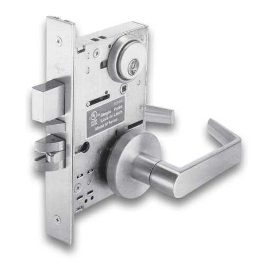
- Page 1 ML3000 Series Mortise Lock Grade-1 Sectional Trim Design Installation Instructions...
- Page 2 OVERVIEW...
-
Page 3: Step 1: Door Preparation
STEP 1: DOOR PREPARATION A. Measure desired height from finished floor, mark a horizontal line on door and door edge. B. Align template on edge of door with applicable horizontal at height line. Check the chart of drilling trim holes on template and mark only holes for lock function being installed. C. M ortise door edge according to measurements of installation template and drill proper holes for trims. D. Recess for face plate, the dimension is L 8-1/32" x W 1-5/16" x D 7/32" (L 204mm x W 33mm x D 5.5mm) . STEP 2: INSTALL STRIKE A. Align strike template on jamb. Be sure to keep 3/8" (9.5mm) distance between lock centerline and strike centerline. Bore 1" (25.4mm) diameter holes into door edge, 1-1/8" (28.6mm) deep. Recess 5/32" (4mm) for flush fit of strike and dust box. B. Mortise jamb according to measurement of strike template. Then fit strike and dust box into frame and secure into place with two (2) strike mounting screws. - Page 4 STEP 3: INSTALL LOCK CASE A. Make sure lock hand to match door hand, use the following diagram to determine the hand of door. B. Instructions for changing lock hand: Change latchbolt handing If the hand of latchbolt does not match door hand, remove fixing screw and pull latchbolt out from lock case, then turn complete unit having the bevel of latchbolt to reverse door handing. Position latchbolt back and fasten it. Set outside hand of lock case The lock case cover side of every lock case assembly finished at factory is made for facing outside of door use.
-
Page 5: Important Note
There are two SET SCREWS located at the bottom of the hub, one on each side. Remove the SET SCREW on the side facing the outside or keyside, and leave the one facing the interior side (inside of the door). If did, the outside lever will function as clutch freewheeling feature. IMPORTANT NOTE: For Passage (F01), Privacy Lock (F02), Store Lock (F14), Room Lock (F21), and Closet/Storeroom Locks SKIP THIS STEP. For Asylum or Institution Lock (F30) REMOVE SET SCREW ON BOTH SIDES. C. C heck the hub of lock case if it is seated in the position as same as the arrow mark "A" which is pointed to "B" hole direction. If yes, to proceed next step. - Page 6 D. Insert lock case into mortise cut-out and fasten screws to door. STEP 4: INSTALL OUTSIDE LEVER ASSEMBLY (Function No. F16, F17, F18 and F29 skip this step.) A. Make sure the direction of outside lever to be installed, then place the reversible spring cage into ferrules with arrow pointing in direction of lever rotation. B. Insert spindle with spring into hub of spring cage on outside lever assembly.
- Page 7 C. I nstall outside lever with mounting posts through door and position spindle with spring into hub of lock case. STEP 5: INSTALL INSIDE LEVER (Function No. F16, F17, F18 and F29 skip this step.) A. Disassemble inside lever assembly by turning the lever bushing with spanner wrench first before next steps. B. Insert spindle with spring into hub of lock case and turn it to double check if latchbolt can be retracted. C. P lace reversible spring cage into ferrules on mounting plate with arrow pointing in direction of lever rotation. D. Install mounting plate onto spindle. Tighten with provided screws.
-
Page 8: Step 6: Install Cylinder
E. Cap inside rose over the mounting plate. F. Screw inside lever into position and tighten lever busing with the spanner wrench. STEP 6: INSTALL CYLINDER A. Loosen cylinder retaining screw to allow the cylinder to be threaded into lock case by inserting a screwdriver into the hole on the mortise lock case. B. Screw the cylinder through the outside face of the door into cylinder hole in lock case. Keyway must end up on bottom of cylinder housing. C. T ighten retaining screw against cylinder by turning screw clockwise. NOTE: For double cylinder, same as above. If first cylinder is installed too far into lock case, second cylinder cannot be properly installed. So, the better way is to use a high cylinder collar. - Page 9 STEP 7: INSTALL THUMBTURN A. Insert thumbtum assembly and project deadbolt. B. Align screw holes on vertical centerline and fasten with screws. NOTE: If the function model does not have thumbtum, skip this step. OR, INSTALL CYLINDER TURN (For function No. F29 only) Put wave spring and cylinder collar onto cylinder turn, then screw cylinder turn into cylinder hole in the lock case through inside face of the door. STEP 8: INSTALL EMERGENCY UNLOCKED ACCESSORIES (For privacy 、 bath room function No: F02, F19 & F22.) A. Emergency Release Plate . If provided, cover it on thumbturn hole at the outside face of the door, and fasten mounting screws to door. . In case emergent situation, remove this outside emergency release plate, and insert a Phillips screwdriver into the thumbturn hole and rotate...
- Page 10 B. Coin Turn . lf provided, install inside thumbturn (without a spindle) as per Step 7. . Insert coin turn spindle into thumbturm hole of lock case and thumbturn hub through the outside face of the door. . Fasten inside thumbturn by two (2) mounting screws, and fix coin turn by provided screws on the outside face of the door. . In case emergent situation, use a coin or flat tip screwdriver to unlock door.
- Page 11 C. Coin Turn Indicator . lf provided, install inside thumbturn (without a spindle) as per Step 7. . Mount indicator base on thumbturn hole which is drilled at the outside face of the door by two (2) base mounting screws. . Insert spindle of coin turn indicator cover into thumbturn hole of lock case, and thumbturn hub through the center hole of indicator base, then cap it onto the indicator base. . Fasten inside thumbturn by two (2) mounting screws, and use provided small screws to fix coin turn indicator cover by hex wrench. NOTE: The installation of this coin turn indicator should be completed prior to the outside and inside lever installing process.
- Page 12 D. Coin Turn Mortise Cylinder If provided, screw coin tum mortise cylinder into cylinder hole of the lock case through the outside face of the door. It is the same way as Step 6. Outside of Door STEP 9: INSTALL ARMOR FRONT Install the armor front onto lock case front and then fasten with supplied screws. Armor face plate MX-I-ML3000 (SM)-19 © 2019 MAAX HARDWARE INC.
Need help?
Do you have a question about the ML3000 Series and is the answer not in the manual?
Questions and answers