
Subscribe to Our Youtube Channel
Related Manuals for NovaTec NovaWheel NWB-DC Series


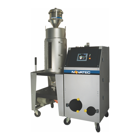
Summary of Contents for NovaTec NovaWheel NWB-DC Series
- Page 1 NovaWheel™ Dry-Convey Dryers NWB-DC – Series, With NovaTouch™ Monochrome Touch Panel PLC MODELS NWB-25-DC through NWB-200-DC) NWB-DC-50 © 2014 NOVATEC, Inc. All Rights Reserved Instruction Manual NWB-DC IM 3 JAN 2014...
- Page 2 DISCLAIMER: NOVATEC, Inc. shall not be liable for errors contained in this Instruction Manual nor for misinterpretation of information contained herein. NOVATEC shall not, in any event, be held liable for any special, indirect or consequential damages in connection with performance or use of this information.
-
Page 3: Table Of Contents
Unpacking Instructions:................6 1.1.3 List of UNPACKED CONTENTS: ............... 6 2.0 BASIC COMPONENTS OF NOVATEC NWB-DC DRYER ASSEMBLY ....7 3.0 ASSEMBLY INSTRUCTIONS ................... 8 3.1 Prepare/Assemble Machine Mount Receiver ............8 3.2 Mount Hopper Receiver & Connect Flex Hose and Pickup Wand ......8 3.3 Positioning the NWB-DC .................. - Page 4 19.8 Rotor Replacement .................... 33 19.9 Seal Replacement ..................... 34 19.10 Drive Motor Replacement ................34 20.0 TROUBLE SHOOTING and ERROR MESSAGES ..........35 21.0 WARRANTY ......................37 ............................© 2014 Novatec, Inc. All Rights Reserved Page 4 NWB-DC IM 3 JAN 2014...
- Page 5 Before installing this system, please read this manual, review the diagrams and the safety information. This should save valuable installation and operation time later and will help ensure safe operation and long life. © 2014 Novatec, Inc. All Rights Reserved Page 5 NWB-DC IM 3 JAN 2014...
-
Page 6: Unpacking For Novawheel™ Nwb-Dc Dry/Convey Models
Hopper Receiver on Fiber Tube Casters, Bolts & Washers (packed (with flapper valve underneath) separately for -150 & -200) 5’ Long Pickup Wand © 2014 Novatec, Inc. All Rights Reserved Page 6 NWB-DC IM 3 JAN 2014... -
Page 7: Basic Components Of Novatec Nwb-Dc Dryer Assembly
NWB-DC IM 3 JAN 2014 2.0 BASIC COMPONENTS OF NOVATEC NWB-DC DRYER ASSEMBLY Hopper Receiver Receiver Mounting Plate VR-5 or VR-12 Alarm Light Machine Mount Panel Receiver Control Panel ON/OFF Switch Panel Power ON Light Material Hopper NWB-DC Dryer Conveying Air... -
Page 8: Assembly Instructions
Hopper Receiver to the nearest EPV Dual Station Vacuum Valve Stub extending from the top of the dryer. (See illustration) © 2014 Novatec, Inc. All Rights Reserved Page 8 NWB-DC IM 3 JAN 2014... -
Page 9: Positioning The Nwb-Dc
Vacuum Valve Stub extending from the top of the dryer. Cut flex hose to length and attach it securely to the stub with a hose clamp. © 2014 Novatec, Inc. All Rights Reserved Page 9 NWB-DC IM 3 JAN 2014... -
Page 10: Electrical Connections
NOTE: Please make sure all electrical connections are tight. It is not common but a loose connection is possible after a long truck ride. © 2014 Novatec, Inc. All Rights Reserved Page 10 NWB-DC IM 3 JAN 2014... -
Page 11: Pre-Cooler Water Connections
NOTE: Cooling water is required if drying temperature is over 225°F. The process airstream must be connected to an external cooling coil if the drying temperature is below 170°F. Contact Factory for Options. © 2014 Novatec, Inc. All Rights Reserved Page 11 NWB-DC IM 3 JAN 2014... -
Page 12: Compressed Air Connection
% of regrind to raise level of cone. You are now ready to proceed to Dryer Setup. See QuickCard attached to dryer. © 2014 Novatec, Inc. All Rights Reserved Page 12 NWB-DC IM 3 JAN 2014... -
Page 13: Sales And Service
Service@novatec.com 10.0 SHIPPING AND INSPECTION Although NOVATEC uses reputed carriers to deliver products, it has no control over the products once it leaves the manufacturing facility. Upon receiving the products, thoroughly inspect all equipment inside and out for damage that may have occurred during shipment. If any damage is found, a claim should be filed immediately with your carrier. -
Page 14: Resin Conveying
11.3 System Flow Diagram NWB-DC System Flow Diagram © 2014 Novatec, Inc. All Rights Reserved Page 14 NWB-DC IM 3 JAN 2014... -
Page 15: Specifications - Nwb-Dc Dry Convey Series
Compressed Air Fittings for Hopper Receivers with Blowback: VR-5-B: 3/8” FNPT, VR-12-B: ¼” FNPT Compressed Air requirements for Blowback: 80-120 psi (5.5-8.3 Bar) *Based on material bulk density of 38 lb./ft © 2014 Novatec, Inc. All Rights Reserved Page 15 NWB-DC IM 3 JAN 2014... -
Page 16: Function Controls
13.6 Conveying Control Provides entry of load/dump times and number of attempted loads before No-Load Alarm is activated plus Blow Back control, if specified. © 2014 Novatec, Inc. All Rights Reserved Page 16 NWB-DC IM 3 JAN 2014... -
Page 17: Pre-Operating System Check
Repeated use of Power Disconnect can cause dryer component failure. 14.2 Checking Electrical Phase Your NOVATEC NWB-DC Dryer includes Phase Detection. This is particularly important for dryers that may be moved around the plant. When you turn the MAIN Disconnect switch to the ON position, a Pop-Up Alarm will appear on the screen if the connection is not correct. -
Page 18: Novatouch™ Control
Select to view the info text of the IO field. Select to confirm your entries or cancel them with . Both actions close the screen keyboard. © 2014 Novatec, Inc. All Rights Reserved Page 18 NWB-DC IM 3 JAN 2014... - Page 19 Other symbols will include: Automatic start is on. Automation 2 set point is on. Language on screen is U.S. English as indicated on Main menu by en-US. © 2014 Novatec, Inc. All Rights Reserved Page 19 NWB-DC IM 3 JAN 2014...
-
Page 20: Screen Maps
NWB-DC IM 3 JAN 2014 15.2 Screen Maps: For all operational functions available to processor: The NOVATEC screen map defines all of the screens provided for all engineering functions: (Available with NOVATEC level password only) © 2014 Novatec, Inc. All Rights Reserved... -
Page 21: Drying Material
Press Hopper Receiver icon to access Hopper Loading screen. Enter desired values and press to start loading hopper from material source previously set up. Press BACK arrow. © 2014 Novatec, Inc. All Rights Reserved Page 21 NWB-DC IM 3 JAN 2014... - Page 22 Machine Mount Receiver ON. Note that Process Heater can be turned OFF or ON using the button at the bottom of the Quick Op screen. © 2014 Novatec, Inc. All Rights Reserved Page 22 NWB-DC IM 3 JAN 2014...
-
Page 23: Additional Control Screens
Then you may select whichever status you want to display. This screen is typically used when viewing parameters from the ground if the dryer is on a mezzanine. © 2014 Novatec, Inc. All Rights Reserved Page 23 NWB-DC IM 3 JAN 2014... -
Page 24: Message Screen - Alarms
Real Time Clock. (See page 20) Remember to press “Disabled Press to Enable” to enable changes AND press it AGAIN when changes are completed to enable Auto Start/Stop. © 2014 Novatec, Inc. All Rights Reserved Page 24 NWB-DC IM 3 JAN 2014... -
Page 25: Password Menu
(which are fine for just about any drying scenario) they will apply to every resin you dry so be sure to re-enter the factory pre-sets. © 2014 Novatec, Inc. All Rights Reserved Page 25 NWB-DC IM 3 JAN 2014... -
Page 26: Intelligent Regen Menu
17.2.6 Features Menu The Features Menu has a dropdown box that displays settings for all activated 17.2.7 Features List features. © 2014 Novatec, Inc. All Rights Reserved Page 26 NWB-DC IM 3 JAN 2014... -
Page 27: Auto 2 Nd Setpoint Menu
When the system is enabled an icon will be displayed on the operations screens in the upper left corner. © 2014 Novatec, Inc. All Rights Reserved Page 27 NWB-DC IM 3 JAN 2014... -
Page 28: Novatec Screens
NWB-DC IM 3 JAN 2014 18.0 NOVATEC SCREENS The NOVATEC MENU can be seen by touching the upper LH corner of any other screen. It can only be accessed with a NOVATEC password. The screen contains the software revision level (in the case of a... -
Page 29: Configuration Menu 3
NOVATEC Service department. 18.1.5 PID Menu These values are pre-set at the factory and should not be changed without first contacting the NOVATEC Service department. © 2014 Novatec, Inc. All Rights Reserved Page 29 NWB-DC IM 3 JAN 2014... -
Page 30: Maintenance Instructions
Compare process temperature setting to hopper inlet temperature Process Heater to make sure they are comparable. Every 2 weeks If they are not - Contact NOVATEC Service Department. Check for leaks or holes. Hose. Tubing & Clamps Every 2 months Tighten or replace as necessary. -
Page 31: Filters
Close the valve after draining. © 2014 Novatec, Inc. All Rights Reserved Page 31 NWB-DC IM 3 JAN 2014... -
Page 32: Chain And Sprockets
Inspect the face of the rotor to see that no surface damage has occurred. The rotor should turn smoothly upon the shaft. Desiccant Rotor Drive Motor © 2014 Novatec, Inc. All Rights Reserved Page 32 NWB-DC IM 3 JAN 2014... -
Page 33: Motor Rotation Signal
Remove the driven sprocket. Slide the Rotor straight & upward, make sure that rotor does not get damaged. Replace the desiccant rotor. To re-install rotor, reverse the above procedure. © 2014 Novatec, Inc. All Rights Reserved Page 33 NWB-DC IM 3 JAN 2014... -
Page 34: Seal Replacement
2. Remove the drive sprocket from the motor shaft. 3. Remove the screws of the motor from the plate. 4. Replace the drive motor. To re-install drive motor, reverse the above procedure. © 2014 Novatec, Inc. All Rights Reserved Page 34 NWB-DC IM 3 JAN 2014... -
Page 35: Trouble Shooting And Error Messages
(Rotor not fully reactivating.) Check set temperature on NWB-DC Reactivation temperature microprocessor controller. it should be controller set too Low 380° F. (190°C) Replace heaters. Reactivation heaters faulty. © 2014 Novatec, Inc. All Rights Reserved Page 35 NWB-DC IM 3 JAN 2014... - Page 36 RPH speed. Rotor drive motor defective. Replace motor NOTE: When ALARM message is followed by a ?, press the message for more information. © 2014 Novatec, Inc. All Rights Reserved Page 36 NWB-DC IM 3 JAN 2014...
-
Page 37: Warranty
Wear resistant options may be available to extend usable service life with abrasive materials. Novatec reserves the right to limit the warranty if the customer installs replacement parts that do not meet the specifications of the original parts supplied by Novatec.
Need help?
Do you have a question about the NovaWheel NWB-DC Series and is the answer not in the manual?
Questions and answers