
Related Manuals for Cascade TFC


Summary of Contents for Cascade TFC
- Page 2 Technical Documentation TFC™ – Touch Force Control CE_Logo.eps Document Number 6863789 Cascade Corp. File No. AU3546 cascade corporation Display Version 6.0.3 Tool Version 335 Cascade is a Registered Trademark of Cascade Corporation...
- Page 3 Click Here To Go To Section Save TFC™ Load Data File (page 3) Click Here To Go To Page Upload New/Updated TFC™ Load Data File (page 5) Click Here To Go To Page Save Configurations Settings (page 7) Click Here To Go To Page...
- Page 4 ONTENTS SECTION (CONTINUED): 16 CONFIGURATION SETTINGS (continued) Change Manual Mode Pressure Values (page 16) Click Here To Go To Page Download Touch History (page 18) Click Here To Go To Page Change Language (page 19) Click Here To Go To Page Change Password (page 20) Click Here To Go To Page Change Date And/Or Time (page 21)
- Page 5 UICK REFERENCE GUIDE HOW TO... REFER TO SECTION: Review kit components 4 Introduction & General FAQ Adjust TFC™ system performance 7 Testing System Prior To Use Change a load’s target pressure value 14 TFC™ Data Tool Change the Default Pressure value...
- Page 6 MPORTANT INFORMATION WARNINGS WARNING: The TFC™ system is not a WARNING: Available maximum clamp safety device. It is intended as a pressure/ pressure is dependent on the truck relief force control device to reduce load damage setting. Set the truck relief higher than the and aid operators.
- Page 7 CLAMP circuit pressure. DATA AS RECEIVED The TFC™ system is delivered with data as specified by the customer on the pre-sale form. IMPORTANT: The end-user must verify the pressures specified for each load description before the truck and attachment are put into operation.
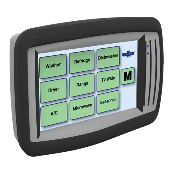
- Page 8 TFC™ SYSTEM DESCRIPTION The TFC™ system is a touch screen system that allows the driver to select the product and load configuration to automatically apply proper clamp force, based on pressure, to the load. The TFC™ system is an improvement over the three-position valve option, offering many more settings.
- Page 9 NTRODUCTION HARDWARE: Display Cable Display Mounting Components Display Flash Drive Pressure Control Power Cable Valve 24V-48V Power Cable Return-To-Tank Kit Voltage Converter AC2877.eps Section 4 6863789...
- Page 10 Confirmation screen (Screen 4). Load Cfg 3 Load Cfg 6 Category AC2779.eps Screen 3 Category The display sends a signal to the TFC™ Pressure Control Valve to set the pressure for the load being Category handled. AC2782.eps Home Screen with Repeat Button...
- Page 11 NTRODUCTION INITIAL TFC SETTINGS The TFC™ system is delivered with the following preloaded: load descriptions (refer to screens shown on previous page for example), target pressure settings and system settings. They are based on the information supplied from the pre-sale form. All of these variables are adjustable.
- Page 12 Custom timer values are optional and can be changed The option is available to set the pressure with only one or by category or by product type in the TFC™ Data Tool. two buttons (one touch or two touch). This is useful for working with a large quantity of the same product.
- Page 13 TFC™ Data Tool: The load data (provided from the pre-sale form) is stored in a table for the display to access. The TFC™ Data Tool is found on the provided USB flash drive and used to change the load data information. The Tool allows the user to add descriptions...
- Page 14 1. How is the data displayed on the touch screen entered or modified? Data is entered or modified using the TFC™ Data Tool which is provided as part of the TFC™ kit. 2. Can the load data file be emailed? Yes.
- Page 15 General FAQs ™ FAQ’s-General 9. Does the setup procedure need to be performed for every truck and clamp combination: Yes. Combining the hydro-mechanical variability of the truck and clamp results in a unique operating environment that will require the set up variables to be set individually from truck to truck.
- Page 16 TFC™ Data Tool? Either psi, bar, or MPa can be used. Conversions are done internally. 23. What is the clamp pressure if the TFC™ unit is OFF or there is no power to the unit? The pressure setting is ultra-low and the arms will normally not close.
- Page 17 Yes, it is rated to IP67. Cascade Corporation • PO Box 20187 • Portland, OR 97294-0187 • USA • 800 CASCADE (227.2233) • Tel 503.669.6257 • Fax 800.693.3768 • Fax 503.669.6367 Cascade Canada Ltd. • 5570 Timberlea Blvd. • Mississauga, Ontario L4W 4M6 • Canada • 800.380.2272 • Tel 905.629.7777 • Fax 905.629.7785 Cascade is a registered trademark of Cascade Corporation.
- Page 18 SECTION 5: CUSTOMER DATA SUMMARY CAN BE FOUND IN THE OWNER’S MANUAL BINDER...
- Page 19 12V-48V UL® Classified Kits This section provides installation instructions for Cascade WARNING: Available maximum clamp TFC™ – Touch Force Control Kits. The kits contain a pressure is dependent on the truck relief touch screen display, display mounting kit, return-to-tank setting. Set and verify that the truck relief kit, pressure control valve, power wire harness and flash is higher than the highest TFC™...
- Page 20 TANK OUT port. Valve Hose Reel Connect a high pressure, OEM approved hose (user Clamp supplied) from the TFC™ pressure control valve CLAMP IN OPEN port to the truck auxiliary CLAMP port. Connect a high pressure, OEM approved hose (user Clamp supplied) from the TFC™...
- Page 21 NSTALLATION 12V-48V UL® Classified Kits ELECTRONIC COMPONENT INSTALLATION NOTE: UL Classified Kits require installation by qualified ® personnel only without major disturbance, cutting, splicing Remove cable or soldering of factory installed wiring. from negative battery terminal Disconnect the cable from the negative battery terminal or as directed by OEM truck manual.
- Page 22 NSTALLATION 12V-48V UL® Classified Kits ELECTRONIC COMPONENT INSTALLATION (CONTINUED) Connect power cable to the cable harness. Connect the power cable to the power source. WARNING: To reduce risk of fire, replace only with the same type and ratings of fuse. The fused power cable is polarity sensitive.
- Page 23 "Tank Out" port. Plug the Return-to-Tank hose. • Cap the "Tank Out" port with a high pressure, steel no. 8 cap on the TFC™ valve. • Remove the positive (+) and negative (-) TFC™ power wires at the truck battery. To enable the TFC™ system: •...
- Page 24 NSTALLATION 12V-48V UL® Classified Kits CHECK TFC™ SYSTEM OUTPUT – Pull the CLAMP handle all the way at full throttle and hold for an additional two seconds. Record the gauge VALIDATING SCREEN TARGET pressure reading, below. Repeat two more times, PRESSURE MATCHES ACTUAL recording the gauge pressure readings.
- Page 25 NSTALLATION 12V-48V UL® Classified Kits CHECK TFC™ SYSTEM OUTPUT – Pull the CLAMP handle all the way at full throttle and hold for an additional two seconds. Record the gauge VALIDATING SCREEN TARGET pressure reading, below. Repeat two more times, PRESSURE MATCHES ACTUAL recording the gauge pressure readings.
- Page 26 Pressure Factor adjustments and determine if the adjustment is satisfactory. If not installed AC2791.eps already, install a pressure gauge in the TFC™ valve gauge port or attachment gauge port. Press the “OK” button after password is entered Determine the Pressure Factor Range based on the target pressure (from previous procedure).
- Page 27 NSTALLATION 12V-48V UL® Classified Kits FINE TUNING OUTPUT PRESSURE For the range to be adjusted, press the “Minus” (CONTINUED) (decrease pressure) and “Add” (increase pressure) buttons to adjust, in 0.01 increments. Limit the A dialog box will show. Enter the target pressure adjustment to values between 0.5 and 1.50.
- Page 28 BLANK Section 6 6863789...
- Page 29 Tool and notice the mistake after modifying and saving the data file? The TFC™ Data Tool automatically backs up the original file when the file is saved to a location with a file of the same name. Open the file with the mistake, enter the correct data and save the file.
- Page 30 6. Can TFC™ be programmed to go direct from the category screen to the confirmation screen? Yes. The display can easily be configured using the TFC™ Data Tool to skip two touches and go directly to the confirmation screen (One Touch) or skip one step and go directly to the load configuration screen (Two Touch).
- Page 31 Set the truck relief higher than target values. Use these instructions after the TFC™ system the highest TFC™ pressure setting. is installed.
- Page 32 NOTE: Refer to Table B for clamp force value tolerance. TABLE B ATTACHMENT CLAMP FORCE TOLERANCES CARTON CLAMP ±A 100 lb (0.44 kN) 150 lb (0.67 kN) 200 lb (0.89 kN) 300 lb (1.33 kN) NOTE: For other attachments, consult Cascade. Section 7 6863789...
- Page 33 ESTING THE SYSTEM PRIOR TO USE (ON-SITE) VALIDATE CLAMP FORCE VALUES (CONTINUED) Single Attachment Procedure Of the three readings (Step 2), choose the clamp force value that falls in the middle of the three. For example, NOTE: For a fleet of attachments, refer to page 7. for a 25D Clamp, high values shown: High Pressure –...
- Page 34 ±A (Table B, page 2), service the clamp to make sure it is operating correctly and arm bearings are in good condition. Continue to Step 11. IMPORTANT: For proper TFC™ system performance, the attachment and truck must be in good working condition, properly serviced and maintained.
- Page 35 ESTING THE SYSTEM PRIOR TO USE (ON-SITE) VALIDATE CLAMP FORCE VALUES (CONTINUED) Clamp fully on the clamp force indicator at full throttle Fleet (More Than One Attachment) and hold for additional two seconds. Record the clamp Procedure force reading, below. Repeat two more times, recording IMPORTANT: Avoid changing the “TFCloadData.csv”...
- Page 36 ESTING THE SYSTEM PRIOR TO USE (ON-SITE) VALIDATE CLAMP FORCE VALUES (CONTINUED) Fleet (More Than One Attachment) Procedure (continued) Medium Pressure – Low Pressure – Change the pressure to 1300 psi (90 bar, 9.0 MPa) Change the pressure to 800 psi (55 bar, 5.5 MPa) (target pressure) using the Medium button or arrow (target pressure) using the Low button or arrow buttons.
- Page 37 After servicing the attachment, repeat Steps 1-9 and then continue to Step 11. IMPORTANT: For proper TFC™ system performance, the attachment and truck must be in good working condition, properly serviced and maintained.
- Page 38 Customer Default Pressure From the Acknowledgement screen, touch the Cascade Logo. NOTE: The TFC™ system uses the “Default Pressure” value while in the Configuration Screen. This can be NOTE: If required, cycle the ignition key ‘Off’ and then useful in troubleshooting or determining the correct ‘On’...
- Page 39 ESTING THE SYSTEM PRIOR TO USE (ON-SITE) FINE TUNING OUTPUT CLAMP FORCE For the range to be adjusted, press the “Minus” (CONTINUED) (decrease pressure) and “Add” (increase pressure) buttons to adjust, in 0.01 increments. Limit the A dialog box will show. Enter the target pressure for adjustment to values between 0.5 and 1.50.
- Page 40 BLANK Section 7 6863789...
- Page 41 STABLISHING CLAMP FORCE FOR A LOAD This section provides guidelines on establishing clamp WARNING: The determination of the force for a load. The TFC™ system adjusts the truck appropriate pressure for secure load CLAMP pressure (not clamp force) to enable Cascade handling is the responsibility of the end attachments to apply a resulting amount of clamp force.
- Page 42 Update existing load data or add new product, load configuration and pressure (not clamp force) information for the appropriate “TFCloadData.csv” file using the TFC™ Data Tool. Refer to Section 14 TFC™ Data Tool. Update the touch screen display. Refer to Section 16 Configuration Settings, “Upload New/Updated TFC™...
- Page 43 (24.5 kN) Pressure gauge - 5000 psi (345 bar, 34 MPa) Install a pressure gauge and supplied fitting in the TFC™ pressure control valve No. 4 O-ring gauge port or attachment gauge port. Power the touch screen display “On”. Access the Manual Mode screen.
- Page 44 Pressure product data or add a product, load configuration(s) and pressure value(s) (not clamp force). Refer to Section 14 TFC™ Data Tool. Be sure to make a new “TFCloadData.csv” file once all the information has been added or updated. 1500 The TFC™...
- Page 45 STABLISHING CLAMP FORCE FOR A LOAD TEST A LOAD’S EXISTING CLAMP (TARGET) PRESSURE VALUE To test the existing CLAMP (target) pressure value for a product, perform the following: Power the touch screen display "On", if necessary. Choose the button(s) for the load. Fully clamp the load at full throttle.
- Page 46 BLANK Section 8 6863789...
- Page 47 Quick Start Guide Use this Quick Start Guide as a reference. Read and use this Quick Start Guide with Operator Guide 6868516. The truck is equipped with a TFC™ Pressure Control Valve. To properly clamp each load, perform the following procedure: Operation TFC™...
- Page 48 Screen 2, if activated. Information area: Timer – Time in “X” seconds without input 1500 and returns to Home screen Pressure Setting (current setting shows) AC2799.eps Select: High, Medium, or Low as a starting point Cascade Corporation 2015 07-2015 Part Number 6868517...
- Page 49 Touch Force Control Operator’s Guide This sheet provides operating instructions for Cascade TFC™ – Touch Force Control system used in conjunction with Cascade attachments. The system requires additional instructions as outlined below. Refer to the attachment’s Operator Guide for safety rules and standard operation...
- Page 50 • Resets the timer in Screen 4 (Confirmation screen). AC2589.eps How To Use The TFC™ Display Read Acknowledgement statement and press the “OK?” button to continue. TFC™ – Touch Force Control Copyright 2014 Cascade Corporation www.cascorp.com I agree to operate this attachment in conjunction with the Operator’s Guide,...
- Page 51 How To Use The TFC™ Display (Continued) Product Category Button When the Home screen appears, choose a product category button. Category IMPORTANT: Some Home Screen buttons may be programmed for special loads. The buttons may jump ahead to Screen 3 Category (Step 5) or Screen 4 (Step 6).
- Page 52 Basic Operation With An Attachment Read Acknowledgement statement and TFC™ – Touch Force Control press the “OK?” button to continue. Copyright 2014 Cascade Corporation NOTE: The attachment will not www.cascorp.com operate until the operator accepts the Acknowledgement statement by I agree to operate this attachment in pressing the “OK?”...
- Page 53 Basic Operation With An Attachment (Continued) When the Home screen appears, choose a Product Category Button product category button. IMPORTANT: Some Home Screen buttons Category may be programmed for special loads. The buttons may jump ahead to Screen 3 (Step 6) or Screen 4 (Step 7). Category Category AC2591.eps...
- Page 54 Basic Operation With An Attachment (Continued) Screen 4 (Confirmation screen) will appear. The following information is available: the selected load configuration (with its product category and product type also listed), timer, and target pressure (if enabled to show). Verify data shown matches the load.
- Page 55 Basic Operation With An Attachment (Continued) After the timer reaches zero, the Home Category gory screen will appear showing a transition alert that will blink two seconds (default setting). Category gory Category gory AC2853.eps After the warning symbol stops blinking, Home Screen Press one of the following: •...
- Page 56 • Home button – Return to the Home screen, Information area: • Another pressure (using the Timer – Time in“X” seconds without input buttons) and returns to home screen Pressure Setting (current setting shows, if enabled) AC2852.eps © Cascade Corporation 2015 07-2015 Part Number 6868516...
- Page 57 Then test with a load to make sure that the attachment • Electrical power to the TFC™ system must be from a operates correctly before returning to the job. Stay circuit that can supply 12 Volts @ 3 Amps and includes clear of the load while testing.
- Page 58 "Tank Out" port. Plug the Return-to-Tank hose. • Cap the "Tank Out" port with a steel no. 8 cap on the TFC™ valve. • Remove the positive (+) and negative (-) TFC™ power wires at the truck battery. To enable the TFC™ system: •...
- Page 59 & Technical FAQ. Disconnect Separate main power valve driver wires from truck key connector power circuit. Refer to Section 6 Installation & Technical FAQ. Attachment Replace display clamps at and/or valve driver high pressure? Replace TFC™ Valve Assembly AC2800.eps 6863789 Section 10...
- Page 60 ROUBLESHOOTING BASIC FUNCTION TROUBLESHOOTING (CONTINUED) Read and From A on acknowledge previous page with the “OK?” button. Home If prompted, Wait five screen enter driver seconds. displayed? identification Home screen Try again. displayed? Home Select load screen category. displayed? Verify quality touch Screen and on target.
- Page 61 Screen Refer to Section 7 the correct updates? Testing System pressure? Prior To Use Timer Replace works? Display Transition alert works (if enabled)? Return button works? Home button works? Back button works? TFC™ System is OK AC2802.eps 6863789 Section 10...
- Page 62 Then turn the truck ignition key 'Off' and then 'On' again. NOTE: Vehicles with 24-48VDC require a DC/DC converter and relay. The TFC system is 12 Vdc. Start Wire Harness Connector (Display) Verify electrical component installation.
- Page 63 ROUBLESHOOTING DISPLAY TROUBLESHOOTING Solution Problem Ignition key does not turn Refer to “System Power Troubleshooting” , page on the display After a reboot the "OK?" button Display does not respond (Acknowledgement Screen) can take up to to touch three or more seconds to respond. Try again. The display screen is pressure sensitive and works well with gloves, stylist or other appropriate tools.
- Page 64 Problem Enter ‘9999’ and then touch the “R” to reset the Custom password forgotten password to the default ‘1234’ . Can’t find Configuration Touch the Cascade logo and enter the Screen password Display is damaged, Replace the Display. cracked, not functioning...
- Page 65 Verify the truck auxiliary CLAMP and OPEN circuit lines are not crossed. Trace the line from the vehicle auxiliary valve clamp function energy port, through the TFC™ valve and into the attachment valve port marked “Clamp” . Remove air by performing the procedure Pressure values are not Section 6 Configuration Settings, “Check TFC...
- Page 66 Verify the clamp FORCE vs Input clamp PRESSURE relationship for the attachment model (consult Cascade) and that the correct correlating pressure value is set in the TFC™ data. Refer Section 8 Establishing Clamp Force, for examples. Use the Pressure Factors (Refer to Section 16 Configuration Settings) to make calibration adjustments to the pressure output.
- Page 67 ROUBLESHOOTING CLAMP CIRCUIT TROUBLESHOOTING (CONTINUED) Solution Problem Use the Pressure Factors (Refer to Section 16 All pressures are too low Configuration Settings) to make calibration and loads slip adjustments to the pressure output. Refer to supervisor or manager to verify pressure values are correct.
- Page 68 BLANK Section 10 6863789...
- Page 69 After each 500 hours of truck operation, in addition to the output 100-hour maintenance, perform the following procedures: • Check TFC™ system pressure output by verifying that the screen target pressure matches the actual gauge pressure (or desired clamp force using clamp force indicator).
- Page 70 ERVICE VALVE REMOVAL AND INSTALLATION WARNING: Before removing any hoses, relieve pressure in the hydraulic system. With the truck off, open the truck auxiliary control valve(s) several times in both directions. Solenoid Connector Disconnect the hoses from the valve. Plug the ends and tag for reassembly.
- Page 71 ERVICE VALVE SERVICE (CONTINUED) O-Rings O-Rings AC0684.eps CL0342.eps Back-up Rings Back-up Ring Priority Flow Control Cartridge Check Valve Cartridge Solenoid Cartridge Solenoid Coil O-Rings Retaining Nut Back-up Ring AC2545.eps Solenoid Valve Cartridge WARNING: After completing any service procedure, always test the attachment through several cycles.
- Page 72 ERVICE HYDRAULIC SCHEMATIC OPEN Attachment Valve CLAMP Gauge Check Valve TFC™ Pressure Port Internal Control Valve Reeving Hose Reel Solenoid Priority Flow Valve Control Valve CLAMP/OPEN Auxiliary Valve Truck Relief Truck Return-To-Tank Valve Hydraulic Fitting Pump Truck Tank AC2594.eps Section 11...
- Page 73 ERVICE ELECTRICAL SCHEMATIC TFC™ Pressure Control Valve Touch Screen Display USB Port 24V-48V Voltage Converter Kit (24V-48V Electric Trucks) Fuse, 5A Fuse, 2A Key, 12V+ Fuse, Switched Key, Fuse, 2A 24V-48V Truck Relay Truck Battery Battery Ground AC2680.eps 6863789 Section 11...
- Page 74 BLANK Section 11 6863789...
- Page 75 ARTS TFC™ – Touch Force Control Kits & )⁄ ¤ ‹ › fi AC0919.eps ∕ Return-To-Tank Kit AC2882.eps 6863789 Section 12...
- Page 76 Cartridge, Check Valve 6061801 Cartridge, Flow Control 609234 Plug, 4 6807816 Return-To-Tank Kit ◆ Part number based on customer data. Contact Cascade to order with original configured data. ▲ Included in Display Mounting Kit 6849297. ● Includes items 19-25. Section 12 6863789...
- Page 77 Default Pressure: _____________ (The pressure supplied to position the arms when no load is selected) Mounting Information: Cascade needs to provide an optional wire harness if the touch screen will be mounted on the engine hood that tilts back to access the engine. Please select a desired location of the touch screen: £...
- Page 78 Providing Clamp Force or Clamping Hydraulic Pressure Data to Cascade: In order to program TFC, the clamp force data for every product to be clamped will need to be provided. Cascade is very flexible in how it receives the data. The following outlines the various ways the one-to-one relationship between clamp force or clamp pressure and the product to be clamped is communicated.
- Page 79 ™ - Examples of Data Structure Carton Clamps Examples when load data is known in terms of clamp pressure (psi, bar or MPa) Quantity Clamp Hydraulic Unit of Clamp Force Unit of Product Name Handled Pressure Measure Specified Measure Category Name (optional) Washer 1500 Laundry...
- Page 80 -Touch Force Control Presale Form ™ Providing Clamp Force or Clamping Hydraulic Pressure Data to Cascade (continued): If Cascade has questions, please provide contact info: Name _________________________________ Phone: ________________________________________ Please enter your load data below using clamp pressure or clamp force:...
- Page 81 “TFCLoadData.csv” file, use • Time values are in seconds. this Tool to begin the process of updating the TFC™ system. • Touch “shortcut“ options are available as a drop down menu. One touch or two touch options will gray out fields.
- Page 82 IMPORTANT: This will overwrite all data present in the Tool. Use with caution. Reset Button – Resets all the values to default Save button – Creates a file for the TFC™ values. IMPORTANT: This will erase all data display to use.
- Page 83 Save button – Creates the file for the TFC™ Home Button – Returns to Home worksheet display to use. Timer Option Column – Each Product Type has Load Configuration Row –...
- Page 84 Earlier versions of Excel will not work and could prevent the Tool from functioning properly. Insert the USB flash drive into a computer USB port. Launch the TFC™ Data Tool found on the root directory of the drive, called “TFC Data Tool.xlsm”. Root Directory on USB Flash Drive: AC2901.eps...
- Page 85 NOTE: Changing the language does not change (translate) the user data entered into the Tool or imported into the Tool. Open the TFC™ Data Tool as described in the “Opening The Load Data Tool”, page 4. In the “Home” screen, click on the Language Selection Button, as shown.
- Page 86 For a written account, log changes using the table on page 16. Open the TFC™ Data Tool as described in the “Opening The TFC™ Data Tool”, page 4. In the “Home” worksheet, add, modify or remove Product Category text into the yellow cells of column labeled “1.
- Page 87 SING THE TFC™ DATA TOOL ADD/MODIFY/REMOVE A PRODUCT TYPE To add, modify or remove a product type, perform the following procedure. For a written account, log changes using the table on page 16. Each Product Category (or Product) listed on the “Home”...
- Page 88 SING THE TFC™ DATA TOOL ADD/MODIFY/REMOVE A PRODUCT TYPE (CONTINUED) Add, modify or remove text for up to six Load Configuration yellow cells for each Product Type row section. • If needed, to add a second line, use the keyboard’s ALT + ENTER key combination.
- Page 89 SING THE TFC™ DATA TOOL CHANGE TIMER OPTION The timer option changes the default time (60 seconds) to clamp a load to a specified time in a Product Category group or specific Product Type. To change the timer option on one or more Product Category or Product Type, perform the following procedure.
- Page 90 SING THE TFC™ DATA TOOL CHANGE TOUCH OPTIONS Touch options are “shortcuts” from the standard sequence of button selections (multi touch). To change touch options, perform the following procedure. For a written account, log changes using the table on page 16.
- Page 91 SING THE TFC™ DATA TOOL CHANGE TOUCH OPTIONS (CONTINUED) Category’s Product Type Worksheet: In the Category’s Product Type worksheet, click on the “Change Timer & Touch Options” button to show the options, if necessary. For each Product Type that requires a change in touch options, click on the corresponding cell in the “Touch...
- Page 92 Once the file is saved, a confirmation dialog box will show with the name of the file. Click the “OK” button. Click the “OK” button If desired, save the TFC™ Data Tool file and close the file. Remove and secure the USB flash drive.
- Page 93 SING THE TFC™ DATA TOOL BACKUP SAVED CSV DATA FILE Creating A Copy And Rename A File From Its Original Name: Insert the USB flash drive into a computer USB port. Open the USB flash drive directory. Move (“Copy” or “Cut” and “Paste”) the file to separate location (such as a computer).
- Page 94 The following procedure imports an existing “TFCloadData.csv” file into the TFC™ Data Tool . This will overwrite the current values in the TFC™ Data Tool. If needed, save a copy of the current values. Refer to the “Saving Data”, page 12.
- Page 95 SING THE TFC™ DATA TOOL RESET TO DEFAULT DATA The following procedure resets the TFC™ Data Tool to it’s original load data values. This is used in situations when a user starts from the beginning and has all new load data.
- Page 96 SING THE TFC™ DATA TOOL Section 14 6863789...
- Page 97 ATALOGGER™ – TOUCH HISTORY Display Version 6.0.3 This section provides instructions to import and review Touch the “Next” button. touch history log(s) downloaded from the TFC™ display. The log(s) contain every touch on the display’s screen, Page 1 Configuration including date, time, screen name and description. A log...
- Page 98 ATALOGGER™ – TOUCH HISTORY DOWNLOAD TOUCH DATA (CONTINUED) To exit, touch the “Done” button. Configuration Back Next Current Time: 4/2/2015 13:52:54 Manual Pressures Data Log “BAR, PSI, Mpa” Change Download Visuals Password Date and Time Load Change Change Done Manual Low : 1000 Trans Alert(sec): 2 Manual Med : 1500 Press.
- Page 99 ATALOGGER™ – TOUCH HISTORY OPENING AND IMPORTING TOUCH HISTORY FILE (CONTINUED) In the “Open” dialog box, change the filter to “All Files (*.*)”. Navigate to the root directory (top level) of the USB flash drive. Left, double click on the “Logs” folder. AC2883.eps Open the desired folder based on the display’s serial number.
- Page 100 ATALOGGER™ – TOUCH HISTORY OPENING AND IMPORTING TOUCH HISTORY FILE (CONTINUED) Locate and choose the desired file: “Log0000X.txt”. Click the “Open” button. AC2885.eps If the “Test Import Wizard” dialog box appears, verify that the following options are selected: Original Data Type: Delimited Delimiters: Tab Column Data Format: General NOTE: Skip to Step 12, if the “Text...
- Page 101 ATALOGGER™ – TOUCH HISTORY OPENING AND IMPORTING TOUCH HISTORY FILE (CONTINUED) Save the file as an Excel document (file type “.xlsx”). Name the file with the display serial number and date or another naming syntax. For example, “log_1408143BB_05202015.xlsx”. IMPORTANT: Saving files to the serial number folder on the USB flash drive will result in the folder and its file(s) being overwritten when the next log(s) are downloaded.
- Page 102 • Selection column: “Safe Operations Agreement” • One blank row is added Screen Selection column column TFC™ – Touch Force Control Copyright 2014 Cascade Corporation ver.: 6865854R0 www.cascorp.com I agree to operate this attachment in conjunction with the Operator’s Guide, which I have read and understand.
- Page 103 (driver) identification was denied. – Selection column: “Cancel“ – the “Cancel” button was pressed. Screen Selection TFC™ – Touch Force Control column column Copyright 2014 Cascade Corporation ver.: 6865854R0 www.cascorp.com I agree to operate this attachment in conjunction with the Operator’s Guide,...
- Page 104 ATALOGGER™ – TOUCH HISTORY REVIEWING TOUCH HISTORY (CONTINUED) Acknowledgment Screen (Continued) Pressing the Cascade Logo: • First, records that the Cascade Logo is pressed: – Screen column: “Agreement” – Selection column: “Access Keypad” • Then, records activity on password dialog box: –...
- Page 105 ATALOGGER™ – TOUCH HISTORY REVIEWING TOUCH HISTORY (CONTINUED) Driver Selection Screens For every button pressed on the operator (driver) selection screens (Home screen, Screen 2, Screen 3 and the Confirmation Screen), the following is recorded: Home Screen (category/product screen, Screen 1) •...
- Page 106 ATALOGGER™ – TOUCH HISTORY REVIEWING TOUCH HISTORY (CONTINUED) Driver Selection Screens (Continued) Screen 3 (load layout screen) • Screen column: “Screen 3” • Selection column: Name of the load layout button that was pressed. For example, the Selection column will list “4 Units”.
- Page 107 ATALOGGER™ – TOUCH HISTORY REVIEWING TOUCH HISTORY (CONTINUED) Manual Mode (if enabled) For every manual mode button pressed on the driver selection screens, Home screen and Screen 2, and Category Category Category Category Refrigeration Laundry Special buttons pressed on Manual Mode Screen, the following is recorded: Pressing the Manual Mode button: Category...
- Page 108 ATALOGGER™ – TOUCH HISTORY REVIEWING TOUCH HISTORY (CONTINUED) Configuration Screens Button Name Box Name While in the Configuration Screens 1, 2 and 3, button(s) Page 1 pressed are recorded as follows: Configuration Next • Configuration Buttons Current Time: 4/2/2015 13:52:54 Data Settings Pressure Factor...
- Page 109 Pressure Factor • Save TFC™ Load Data file (page 3) Load Save Load Save Change • Upload new/updated TFC™ Load Data file (page 5) Manual Mode: Language Default Pressure • Save a Configurations Settings (page 7) Change Change • Upload a Configurations Settings file (page 9) •...
- Page 110 ONFIGURATION SETTINGS ACCESS CONFIGURATION SCREEN Power the unit and let it boot to the Acknowledgement screen. Touch the Cascade Logo. TFC™ – Touch Force Control Copyright 2014 Cascade Corporation ver.: 6865854R0 www.cascorp.com I agree to operate this attachment in conjunction with the Operator’s Guide, which I have read and understand.
- Page 111 SAVE TFC™ LOAD DATA FILE Perform the following steps to create a copy of the current TFC™ load data file on the display. A dialog box with a keyboard will show. Enter a three digit suffix as part of naming the file. All files begin with Plug a USB flash drive into the USB connector found on “TFCloadData_”...
- Page 112 ONFIGURATION SETTINGS SAVE TFC™ LOAD DATA FILE (CONTINUED) Once the file saves onto the USB flash drive, a message will show “Data Saved Successfully”. NOTE: If the message “Cannot write data file...” appears, verify that the USB flash drive is plugged into USB connector.
- Page 113 In the “Data” box, touch the “Load” button. DATA FILE Perform the following steps to upload a “TFCloadData.csv” file the TFC™ display. This file is created using the Load Data Tool. NOTE: The file must be on the root directory (top level) of...
- Page 114 ONFIGURATION SETTINGS UPLOAD NEW/UPDATED TFC™ LOAD DATA FILE (CONTINUED) The file will be automatically loaded. When finished, a message will show “Data Update Successful.” Page 1 Configuration Next Current Time: 4/2/2015 13:52:54 Data Settings Pressure Factor Load Save Load Save...
- Page 115 ONFIGURATION SETTINGS SAVE CONFIGURATION SETTINGS In the “Settings” box, touch the “Save” button. Configuration settings are settings for the TFC™ system. Changes to Configuration settings include: • Show or hide Manual Mode • Changes to High, Medium or Low Pressure Factors...
- Page 116 ONFIGURATION SETTINGS SAVE CONFIGURATION SETTINGS (CONTINUED) Once the file saves onto the USB flash drive, a message will show “Settings Saved Successfully”. NOTE: If the message “Cannot write settings file...” appears, verify that the USB flash drive is plugged into USB connector.
- Page 117 In the “Settings” box, touch the “Load” button. Configuration settings from one TFC™ display can be loaded onto other TFC™ displays that are a part of a fleet of attachments. To upload a configuration settings file (“Settings.csv”) that was previously saved, perform the...
- Page 118 ONFIGURATION SETTINGS UPLOAD CONFIGURATION SETTINGS FILE (CONTINUED) The file will be automatically loaded. When finished, a message will show “Settings Update Successful.” Page 1 Configuration Next Current Time: 4/2/2015 13:52:54 Data Settings Pressure Factor Load Save Load Save Change Manual Mode: Language Default Pressure Change...
- Page 119 In the “Default Pressure” box, touch the “Change” button. The Default Pressure is the pressure that is set by the TFC™ system when there is no load specified. The TFC™ Page 1 Pressure Control Valve sets the pressure to the Default...
- Page 120 Pressure Factor adjustments and Cancel determine if the adjustment is satisfactory. If not installed already, install a pressure gauge in the TFC™ valve gauge AC2791.eps port or attachment gauge port. Press the “OK” button after...
- Page 121 ONFIGURATION SETTINGS ADJUST PRESSURE FACTORS A dialog box will open for adjusting pressure factors. (CONTINUED) • Use a pressure gauge to monitor the pressure changes to the system, during clamping, as a In the “Default Pressure” box, touch the “Change” pressure factor is adjusted.
- Page 122 Repeat Step 5 and 6 to change the default pressure back to the customer’s original Default Pressure, as noted in Step 4. If all changes are complete to the TFC™ configuration settings, save the settings. Refer to “Save Configuration Settings”, page 7.
- Page 123 Yes = On NOTE: The default password is “1234”. The password No = Off can be changed. Refer to “Change Password”. If all changes are complete to the TFC™ configuration **** settings, save the settings. Refer to “Save Configuration Settings”, page 7.
- Page 124 Configuration Back Next Current Time: 4/2/2015 13:52:54 Manual Pressures Data Log “BAR, PSI, Mpa” Change Download TFC™ – Touch Force Control Visuals Password Date and Time Copyright 2014 Cascade Corporation Load Change Change ver.: 6865854R0 www.cascorp.com Done Manual Low : 1000...
- Page 125 AC2826.eps Verify the settings by viewing the summary information at the bottom of the Configuration screen. If all changes are complete to the TFC™ configuration settings, save the settings. Refer to “Save Configuration Settings”, page 7. To leave the Configuration screen, touch the “Done”...
- Page 126 Plug the USB flash drive into the USB connector found NOTE: When the “Download” button is pressed (in on the TFC™ harness near the display. the “Data Log” box), a subfolder (in the logs folder) is created on the USB flash drive and named with the serial Touch the Cascade Logo.
- Page 127 Touch the Cascade Logo. English Español Português Pycc Français Deutsch Svenska Suomi TFC™ – Touch Force Control Copyright 2014 Cascade Corporation Italiano Türkçe ver.: 6865854R0 Nederlands www.cascorp.com Cancel I agree to operate this attachment in conjunction with the Operator’s Guide, which I have read and understand.
- Page 128 Manual Med : 1500 Press. Fact. Low: 1.1 Pressure: Hide Manual High : 1900 Press. Fact. Med: 0.98 Manual Mode: No TFC™ – Touch Force Control Default : 900 Press. Fact. High: 1.02 Pressure Units: PSI Copyright 2014 Cascade Corporation AC2832.eps ver.: 6865854R0...
- Page 129 “BAR, PSI, Mpa” Change Download Visuals Password Date and Time Load Change Change TFC™ – Touch Force Control Done Manual Low : 1000 Trans Alert(sec): 2 Copyright 2014 Cascade Corporation Manual Med : 1500 Press. Fact. Low: 1.1 Pressure: Hide ver.: 6865854R0 Manual High : 1900 Press.
- Page 130 Press. Fact. High: 1.02 Pressure Units: PSI AC2837.eps Cancel AC2791.eps If all changes are complete to the TFC™ configuration Press the “OK” button after settings, save the settings. Refer to “Save Configuration password is entered Settings”, page 7. To leave the Configuration screen, touch the “Done”...
- Page 131 Manual Low : 1000 Trans Alert(sec): 2 Manual Med : 1500 Press. Fact. Low: 1.1 Pressure: Hide If all changes are complete to the TFC™ configuration Manual High : 1900 Press. Fact. Med: 0.98 Manual Mode: No Default : 900 Press.
- Page 132 Pressure Hidden Touch the Cascade Logo. Touch the “Next” button to access page 3 of the Configuration screen. Configuration Back Next TFC™ – Touch Force Control Current Time: 4/2/2015 13:52:54 Copyright 2014 Cascade Corporation Manual Pressures Data Log “BAR, PSI, Mpa”...
- Page 133 SHOW/HIDE PRESSURE (CONTINUED) Verify the setting by viewing the summary information at the bottom of the Configuration screen. If all changes are complete to the TFC™ configuration settings, save the settings. Refer to “Save Configuration Settings”, page 7. To leave the Configuration screen, touch the “Done”...
- Page 134 Load Save Change updated “VISU” file folder, into the USB connector found Manual Mode: Language Default Pressure on the TFC™ harness near the TFC™ display. Change Change Touch the Cascade Logo. Done Manual Low : 1000 Trans Alert(sec): 2 Manual Med : 1500 Press.
- Page 135 Pressure Units: PSI AC2859.eps “Yes” = currently disabled “No” = currently enabled Cancel If all changes are complete to the TFC™ configuration settings, save the settings. Refer to “Save Configuration AC2791.eps Settings”, page 7. Press the “OK” button after To leave the Configuration screen, touch the “Done”...
- Page 136 The login workbook in this format?”, choose the “Yes” button. identification is case specific. The file is ready to upload into the TFC Display. Close the file in Excel. Remove the USB flash drive from the computer.
- Page 137 Next Plug the USB flash drive into the USB connector found Current Time: 4/2/2015 13:52:54 Manual Pressures Data Log “BAR, PSI, Mpa” on the TFC™ harness near the display. Change Download Touch the Cascade Logo. Visuals Password Date and Time...
- Page 138 BLANK Section 16 6863789...
- Page 139 ONFIGURATION SETTINGS TFC™ – Touch Force Control Settings Changes Log (IMPORTANT: Always create a backup copy of previous versions of the file.) Truck & Attachment: Settings File Name: Pressure Factor Values Manual Mode Pressures Default Pressure Date/Set By HIGH HIGH...
- Page 140 ONFIGURATION SETTINGS TFC™ – Touch Force Control Settings Changes Log (IMPORTANT: Always create a backup copy of previous versions of the file.) Truck & Attachment: Settings File Name: Psi/Bar/MPa Pressure Manual Mode Transition Toggle Toggle Language Alerts Date/Set By Show/Hide...
- Page 141 Configuration Screens Target Pressure Three screens on the display with TFC™ system settings. The pressure that the Pressure Control Valve is set to for clamping a specific load. Confirmation Screen A screen that shows the result of driver selections, a timer TFC™...
- Page 142 PPENDIX GLOSSARY Touch History A record of every screen touch with data and time stamp. Touch Screen Display An interactive display for the driver to select the product and load configuration through a sequence of button selections. Transition Alert A warning that flashes on the display to advise the driver the system has transitioned back to the default pressure.
- Page 143 BLANK...
- Page 144 Do you have questions you need answered right now? Call your nearest Cascade Service Department. Visit us online at www.cascorp.com AMERICAS Cascade do Brasil Cascade Corporation Cascade Canada Inc. Praça Salvador Rosa, U.S. Headquarters 5570 Timberlea Blvd. 131/141-Jordanópolis, 2201 NE 201st Mississauga, Ontario São Bernardo do Campo - SP...
Need help?
Do you have a question about the TFC and is the answer not in the manual?
Questions and answers