Table of Contents
Advertisement
Quick Links
Advertisement
Table of Contents

Summary of Contents for GEOSAT Electronic Eye
- Page 1 INSTALLATION MANUAL...
-
Page 2: Table Of Contents
5.3. External Sensor .................... 11 6. WEB CONFIGURATION ................12 6.1. Access passwords ..................12 6.2. Web access ....................13 6.3. Electronic Eye configuration ................15 7. SETTING THE CAMERA ANGLE ..............20 8. CORRECT OPERATION VERIFICATION ............23 9. LED STATUS ..................25 10. -
Page 3: Introduction
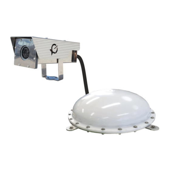
The Electronic Eye is a fully integrated and stand-alone system: No installation needed at the bridge. No need of additional equipment. Just needs to be connected to the power supply. Page 3/28... -
Page 4: Precautions Before Installation
The part of the antenna with connectors must be facing down. DC power for Electronic Eye In the Electronic Eye with 24Vdc cable, this cable should not be short-circuited in any case. Check with Marine Instruments for DC power. Magnetic switch to turn on batteries People with pacemakers should not handle the equipment unless they are sure that the pacemaker will not be affected by the magnetic field. -
Page 5: Installation Diagram
. IM010ES10 3. INSTALLATION DIAGRAM Page 5/28... -
Page 6: Antenna And Camera Installation
. IM010ES10 4. ANTENNA AND CAMERA INSTALLATION STEP 1. Select a clear area with good GPS coverage for the installation of the device. STEP 2. Place the antenna supports in the antenna. STEP 3. Fix the antenna. In order to do this, use the U-bolts and the bracket supplied with the equipment. - Page 7 . IM010ES10 STEP 4. Connect the base of the antenna to the ground. Use the material provided by Marine Instruments. STEP 5. Fix the camera support to the vessel rail, using the U-bolts and the supplied nuts and bolts. Connect the support to the ground. STEP 6.
-
Page 8: Cable Installation
. IM010ES10 5. CABLE INSTALLATION 5.1. LED legend Page 8/28... -
Page 9: Cable Connection
. IM010ES10 5.2. Cable connection STEP 1. Connect the camera cables to the base unit. Up to three cameras can be connected to every base unit. Camera connectors are marked with: “CAM1”, CAM2” and “CAM3”. STEP 2. Remove the magnet and check that all the LEDs are on (see image). After checking, place it back. - Page 10 . IM010ES10 STEP 4. Verify the following sequence: a. For equipment installed outdoors, the sequence will be as follows: b. For systems installed indoors: STEP 5. Fix the seal box. Once the seal box is installed, close and place the supplied padlock. Page 10/28...
-
Page 11: External Sensor
. IM010ES10 5.3. External Sensor In the expansion connector it is possible to connect an external sensor: Closed contact Sensor. PNP Sensor. An analogic sensor can also be connected. The connection for these sensors are labelled as “EXP”. Both for installing an external sensor or an analogic sensor, please, contact Marine Instruments. -
Page 12: Web Configuration
WIFI name and WIFI PASSWORD on the card and the key holder card supplied with the equipment. For web configuration of Electronic Eye: Web address: WEB ACCESS on the card or the key holder card supplied with the equipment. -
Page 13: Web Access
To configure the equipment and start working with Electronic Eye, follow these steps: STEP 1. Once the equipment is on, the Wi-Fi spot with the name of the Electronic Eye will appear. Click on it and then click Connect and enter the password provided (WIFI in the key holder card supplied with the equipment). - Page 14 In the home page, the following options appear: Current view os the cameras in the web. See section “Camera position”. Shows the information of the last image taken. Access to the Electronic Eye configuration. STEP 5. Click on “Configure cameras”. Page 14/28...
-
Page 15: Electronic Eye Configuration
In the section “Configure camera” the following configuration criteria appear: Name of the vessel. Only letters (except ñ) and numbers. Should not use blank spaces or special symbols. Same name for all the Electronic Eye on board. WI-FI transmission channel used by Electronic Eye Camera auto-focus... - Page 16 . IM010ES10 Threshold speed under which the system will start the fishing mode. Maximum duration of fishing mode. Trigger frequency during fishing mode. Trigger frequency when the system is not on fishing mode. Number of pictures taken after the last sensor signal. Time taking pictures after 220V power cut.
- Page 17 GPS coverage but DO NOT transmit data via Iridium. INSIDE USE. This configuration applies to Electronic Eye installed inside the vessel. These do NOT have GPS coverage and do NOT have Iridium satellite transmission.
- Page 18 . IM010ES10 Configuration settings To configure the settings of the camera follow these steps: Page 18/28...
- Page 19 . IM010ES10 Type in the name of the vessel (only numbers and letters). Select the copy mode to external device: “Copy all to fill external USB memory”. Select the camera mode of operation: a. Outside use (Master): select “Deck master tracking camera”. b.
-
Page 20: Setting The Camera Angle
. IM010ES10 7. SETTING THE CAMERA ANGLE STEP 1. Access Wi-Fi spot of the Electronic Eye we want to set the camera angle. Click on connect and type in the password supplied (PW WIFI in the key card holder). STEP 2. - Page 21 . IM010ES10 Example of camera setting in tropical seiner for tuna fishing: MAINTOP In purse seiner, it is recommended to focus the port side, where the net is collected, this way you will be able to see the whole fishing operation and the speedboat passing by. Page 21/28...
- Page 22 . IM010ES10 Example of camera setting in tropical seiner for tuna fishing: MAINTOP In purse seiner, it is recommended that the camera points at the hole where the fish will be unloaded as well as the movement of the brailer as in the image below. STEP 5.
-
Page 23: Correct Operation Verification
STEP 3. Check the current view of the cameras at real time: a. Access the WiFi spot of the Electronic Eye we want to verify. Click on Connect and the password supplied (PW WIFI of the key holder card). b. Open an Internet browser (Google Chrome or Mozilla Firefox. It is recommended not to use Windows Internet Explorer) and write the IP address 192.168.99.1 (included in the... - Page 24 . IM010ES10 User and password of the key card holder can only be used by the observer. d. To access the current view of the cameras, click on “Current view camera”. In this screen, you will see the images that have been taken approximately every 5 seconds. It might be necessary to refresh the page of the browser once in a while to see the image.
-
Page 25: Led Status
. IM010ES10 9. LED STATUS LED STATUS MEANING System off. Normal operation. Taking photos. Sensor on. No GPS signal. Transmitting via satellite and battery charge check. Battery failure. Power cut. System suspended. System downloading data from USB external port. In inside use systems: With no GPS signal this led will be off. Page 25/28... -
Page 26: Characteristics
. IM010ES10 CHARACTERISTICS The Electronic Eye version without sensor is powered by AC. The Electronic Eye version with sensor are powered by AC or DC. Consumption table P.max. Consumption 1 camera 625mA 2 cameras 830 mA 3 cameras 1,1 A... - Page 27 . IM010ES10 Dimensions and weight CÁMERA ANTENNA+BRACKET Weight: 4,60 Kg Weight:5,1Kg (Antena) + 0.83 Kg (Soportes) Dimensions: 0.18x0.32x0.16 m Dimensions of the set: 0,33x0,16x0,49 m Page 27/28...
- Page 28 . IM010ES10 Warranty conditions of this product are available at geosat website. Jl. Bungur Besar Raya No 85. Kemayoran - Jakarta Pusat 10620 ( Indonesia ) Tel: + 62 21 420 5318/19 sales@geosat.co.id www . geosat.co.id Page 28/28...
Need help?
Do you have a question about the Electronic Eye and is the answer not in the manual?
Questions and answers