Table of Contents
Advertisement
Quick Links
R
C
R
C
By selecting this VC product you have chosen a professional
device, which guarantees highest possible quality and
Please read the following instructions carefully before
comissioning the product in order to be able to take full
advantage of all quality features regarding this product line.
Änderungen in Technik, Design und Ausstattung vorbehalten
Installations- und Betriebsanleitung
Mounting and Operating Manual
Dear Customer!
reliability.
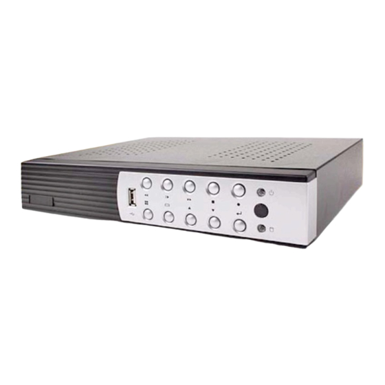
Streamserver
Art.No.: 12544-SF
Art.No.: 12588-SF
Art.No.: 12566-SF
©
All contents of this document may change without prior notice
MO_12544-SF/16.04.2012
MO_14511-K
Advertisement
Table of Contents

Summary of Contents for VC 12544-SF
- Page 1 Installations- und Betriebsanleitung Mounting and Operating Manual Dear Customer! By selecting this VC product you have chosen a professional device, which guarantees highest possible quality and reliability. Please read the following instructions carefully before comissioning the product in order to be able to take full advantage of all quality features regarding this product line.
-
Page 3: Table Of Contents
Table of contents 1 Overview ......................4 1.1 Control bar....................... 8 1.2 Rear Panel Connector..................... 9 1.3 Remote Control ....................... 10 2 Installation ......................11 2.1 Video format detection ..................... 12 2.2 Connection Overview ....................12 2.2.1 Preparing of connections.................. 12 2.2.2 Connections descriptions ................. - Page 4 3. b.7 Channel Recording Setup ..................40 3. b.8 Motion Setup 3. b.9 Authentication Setup .................... 44 3. b.10 System Setup ..................... 44 3. b.11 Hardware Setup ....................51 3. b.11.1 Query Error Messages ................51 3. b.11.2 HDD Setup ....................52 3.
- Page 5 7 PC Viewer & Web Browser Viewer..............83 7.1 PC Viewer Installation ....................84 7.1.1 Overview......................84 7.1.2 Connect PC Client ................... 85 7.1.3 Playback pause ....................87 7.1.4 Record a freeze frame..................87 7.1.5 Remote Playback ..................... 88 7.1.6 Remote Configuration..................93 7.2 Web Browser Viewer....................
-
Page 7: Overview
Chapter Overview... -
Page 11: Control Bar
1.1 Control Bar Button / Name Function PC Connection PC via USB 2.0 for firmware upgrading or Video Backup REW Fast Rewind II PLAY Play/Pause FF Fast Forward STOP Stop playing / recording, open the PTZ menu Start or stop the backup recording ●... -
Page 12: Rear Panel Connector
RJ45 for network connection VGA-OUT VGA Output VIDEO-OUT Video Output AUDIO-OUT Audio Output SENSOR Alarm input “1~4” and common connection “G” (no Function) RS-485 RS-485 connection (no Function) AUDIO-IN Audio input VIDEO-IN BNC Video input: CH1~CH4 (12544-SF), CH1~CH8 (12588-SF) CH1~CH16 (12566-SF) -
Page 13: Remote Control
Press AUTO button to start screen auto sequence. MODE Display mode : switch Picture/x4/x8 display. - ZOOM OUT + ZOOM IN 1,2,----16 Select the camera 1-4 ( Art No. 12544-SF ) 1-8 ( Art No. 12588-SF ) 1-16 ( Art No. 12566-SF ) -
Page 14: Installation
Chapter Installation... -
Page 15: Video Format Detection
2.1 Video format Detection The Video-Streamserver automatically detects the video format of the camera connected (NTSC or PAL) as soon as the cameras are connected and the device is turned on. Please look into the "Hardware Setup" from the automatic NTSC / PAL detection 2.2 Connection Overvierw Make all connections to the peripheral devices before turning on the Video- Sreamserver. - Page 16 8-- Channel BNC-Video Stream Server Alarm inputs and RS-485 interface (optional) Mouse LCD Monitor Power Cameras Network cable Video Monitor Supply 16-Channel BNC- Video Stream Server Alarm inputs and RS-485 interface (optional) Mouse LCD Monitor Power Cameras Network cable Video Monitor Supply...
-
Page 17: Connections Descriptions
2.2.2. Connection descriptions Camera connection Depending on the model, 4 or 8 video inputs are available. Connect the camera via a BNC cable to the video inputs of the Video-Streamserver. Monitor connection Connect the video output "VIDEO OUT" of the video stream server via a BNC / Chinch plug to the video input of a video monitor. -
Page 18: Getting Started As A Streaming Server
Chapter Getting Started of the Video-Streamserver... -
Page 19: Functional Description
3.a.1 Function description If the computer is connected to the network, then the achieved by access is using the browser (Mozilla Firefox). The video sequence of the camera you selected will be displayed in a separate window. Thereby it is possible to embed the video stream to other software (However the compatibility has to be tested due to the variety of the software options). -
Page 20: Configuration Of Streamservers
3.a.2 Configuration of Video-Streamserver After all the components of the video system have been installed, turn on the device. The unit takes a few seconds to check all internal components. Then the device is in live mode. Release Date: May 25 2010 17:33:16 Video: PAL 3.a.3 Main menu... - Page 21 Main menu MAIN MENU Icon Name Function Power Supply To restart or shut down the Video Stream Server This made the settings on the channels: video quality, Channel Setup color, channel name. settings of the recording schedule, video performance Record Setup and video quality.
-
Page 22: Authentication Settings
3.a.4 Setup Authentication Here is the creation of users, the assignment of user rights and the passwords changes. Inactiv Account : Inactivated Account : Account ist in use : Allows access to this feature : Access denied : Creates a new user Deletes a user ID Account: Select the name of the account... -
Page 23: Network Setup
3.a.5 Network connection Use this menu to adjust the device to the network in which it is to be integrated. 3.a.5.1 Activate Network [ Activate]: An access over the network is possible. [ Deactivate]: An access over the network is not available 3.a.5.2 IP-Address setting IP Type... - Page 24 SUBNET MASK: The subnet mask specifies how many IP addresses are included in the computer network . In conjunction with the IP address of a device it determines which IP address is looking for this device in its own network and what it is trying to achieve through routers on other network in conjunction with the IP address of a device it determines which IP addresses looking for this device in its own network and what it is trying to achieve through routers on other networks.
-
Page 25: Configuration For Access Via Pc
3.a.6 Browser configuration to access via PC Access via Network Via Browser: - Firefox - Internet Explorer - Safari Including live stream on Website or Software. Acces via Firefox Website If you choose the access via Browser will be displayed single picture on a monitor screen. - Page 26 Access via Mozilla Firefox Browser To display an image on a PC connected to a LAN or WAN and accessed via browser, it is to be taken into account that certain components and accessories of this, like IP ID Address System, Connection port, Video compression method, resolution, Refresch rate , number of channels etc I IP address of the stream server...
- Page 27 Mozilla Firefox configuration for connection of more than 6 Videostreams "Mozilla Firefox" allows the access of 6 streaming video signals and displays them simultaneously. To display more than 6 streaming video signals on a PC ( up to 16 is possible), the browser has to be configurated as follows.
- Page 28 PC Access via Internet Explorer and Safari Browser The access to the stream server via an Internet Explorer (even with IE on Windows Mobile) and Safari. This requires a different address format. By adding an address extension behind the IP and the port address Port: /m/m.html, the streaming connection will be achieved.
-
Page 29: Getting Started As A Dvr
Chapter DVR function Getting Started... -
Page 30: Switch On The Dvr
3.b.1 Switch on DVR function The DVR is ready for operation after all peripherials have been properly installed. The DVR may take a few seconds to startup by checking all the components. Then, the display live picture mode is setting. When the hard drive is detected by the system it will ask whether or not you would like to format it. -
Page 31: Live Pictures
3.b.2 Home screen Live picture mode The start screen is the starting point for all functions that can be run on the device 1% 2010/06/06 15:37:47 3.b.2.1 The state Bar The state Bar can be found on the top of the sceen. It contains the statur ans notification icons of the surveillance system. -
Page 32: Control Bar Information
3.b.2.2 The Control Bar The Control Bar can be found by panning your mouse towards the bottom part of the sceen. It may be used to switch displays, open and setup channels and their related applications. Icon Function Icon Function Channels Views Load default channel display location 4-channel Split View... -
Page 33: Drag And Drop Channel Swap
3.b.2.3 Drag and Drop Channel Swap The Drag and Drop Channel Swap enables swap the channel displays using your mouse. Move the cursor onto the channel-square » 1% 2010/06/06 15:37:47 you would like to shift. Press left-button of the mouse ( a hand »... -
Page 34: Main Menu
3.b.3 Main menu Logging In fort he First Time Press the icon or the icon and enter the password to get into the main menu. Default password is: 123456 Press the icon to exit the password dialog. Main menu ... -
Page 35: Channel Setup
Icon Name Function Configures error messages checks, hard drive Hardware Setup information, owerwrite setting, network settings,and screen settings. These are used to format USB devices, to update Zusatzeinstellungen firmware, to export event logs, and to restore (Utility/Tools) system settings. Exit Exit the main menu. -
Page 36: Basic Settings
Operation icons Press the icon to expand the menu and view its contents. Press the icon to minimize the menu contents. Click on the right button of your mouse to go back to the upper menu 3.b.4.2 Basic Settings 3.b.4.2 .1 Active Channel Activate one channel or all of the channels. -
Page 37: Default Color Settings
3.b.4.3 Standard color adjustment Adjust the video parameters for each channel or simultaneously for all channels. Brightness: Default is 10 Press the button “◄ / ►”, to adjust the brightness from 1 to 20. Contrast: Default is 10 Press the button “◄... -
Page 38: Performance To Enable
3.b.5.2 Activate Performance Gains The function enables system auto increase the recording power to the heavy loading channel from the not triggered or not recording channels. 3.b.5.3 Record Schedule The record Schedule is a menu charting the recording schdule of a particular channel or all channels fort he wohole day ( 24 hours) and entire week ( 7 days) . - Page 39 3.b.5.3.2 Recording Mode Select There are five recording modes: None: Indicates that the channel is set to not recording during this situation Time: Indicates that the channel is set to continuously record during this situation Motion : Indicates that the channel is set to record when the motion – triggered during this situation Sensor : Indicates that the channel is set to record when the sensor is...
- Page 40 3.b.5.3.3 Schedule Quick programming Select the recording mode ( Motion ) by pressing the Icon to set the recording mode globally : the whole week ( 7 days) and whole day ( 24 hours) are in the same mode.The confirm with the enter buttom ”” . Press the icon “...
- Page 41 Select “” to set the same mode for a specified time every day. Confirm with ”” The following example shows that from 23:00 – 24:00) every day there is no recording ( set to „NONE“ recording mode) Confirm with ”” . You can also specifically set the recording mode for a particular time and day.
-
Page 42: Total Power
3.b.6 Total Power It shows the number of recording power that has been allocated and the total number of recording power. NOTE : For PAL the total power for 4 Ch and 8 Ch is 200/200 ( Power/sec ) and 16 Ch is 400/400 (Power/Sec) To distribute the recording power into four channels by click the total power ( as indicate as above). -
Page 43: Channel Recording Setup
3.b.7 Channel Recording Setup The channel Recording Setup is used to adjust the resolution, quality, frame rate and performance gains of recording. 3.b.7.1 Channel Number Select the icon “ ” (for 4 Ch) or “ ” (for 8 Ch) or (for 16 to setup all channels at one time. -
Page 44: Motion Setup
3.b.7.6 Detector Setup Channel number to choose the channel Alarm Setup Light Detect Mode Light Detect alarm mode Blind Detect Mode Video Loss Mode Video Loss alarm 3.b.8 Motion Setup Motion Setup is accessed to configure the motion mode for the DVR. NOTE Remember to setup the motion mode period on „Record Schedule“... - Page 45 Enable: Activates motion-triggered detection even when the device is in a different recording mode. When enabled, a blink motion icon will be found alongside the Time Recording mode when motion is detected. Disable: Deactivates motion-triggered detection even when the device is in a different recording mode.
- Page 46 3.b.8.6 Motion Detection triggering Full Screen display Trigger Full Screen is the duration of the full-screen display when a channel is triggered. This may be set to a period between 1 to 30 sec. “ OFF”. It will not display on full screen when the channel has been triggered. Also, the trigger area will turn to a red color.
-
Page 47: Authentication Setup
3.b.9 Authentication Setup Authentication Setup manage the authorization for accounts, passwords, and permissions. : Indicates a disabled account : Indicates an active account : Permits access to function : Disables access to function : Creates a new account : Deletes an account Account ID: Enter characters as the account ID Password:... -
Page 48: System Setup
3.b.10 System Setup Click on the System Setup or „System Setup“ “ ” on the Main Menu. Language Selection Language Selection is used to select the language fort he on-screen display Menu (OSD) View Setup View Setup is for choosing whether to display certain illustrations and information or not. - Page 49 Main Menu Graphics Mode Sets the main menu displayed by graphic icons or text mode Channel Dynamic Effect Enables or disables the channel moving effects during channel dynamic drag and drop Icon Help Enable or disables the help icon text description to appear when the mouse hovers over the icons.
- Page 50 Date/Time Setup Date/Time Setup sets relevant information on date and time. Date Display Mode Date Display Mode is used to choose a date format for the state information.The llowable formats are : YYYY/MM/DD, DD/MM/YYYY und MM/DD/YYYY. Time Set „Time Set“ is for adjusting the date and time. ...
- Page 51 NTP SERVER NTP ( Network Time Protocol) allows for the synchronisation of the day/time settings with the NTP server through Internet. Activate Service : Icon Enable : Enable Synchronisation Icon : Disable Synchronisation SERVER IP. The IP address of NTP server ( Maximum in 24 characters) Interval ( Days) : The frequency ( number of days ) of when the server is synchronized.
- Page 52 Sequence Setup The Sequence Setup Menu is setting fort he channel rotation sequence period. Full Screen Sequence Enables or disables the full screen rotation period. 4 Split Sequence Enables or disable the 4 split display rotation period. 1+7 Split Sequence Enables or disable the 7+1 split display rotation period.
- Page 53 Mouse Repeat Speed: OFF, Slow, Normal, Fast Langsam, Normal, Schnell IR Geschwindigkeit: OFF, Slow, Normal, Fast Auto Exit Menu The Auto exit Menu configures the menu to automatically revert back to the main display screen after a specified period. The period can be selected between 10, 20, 30, 40, 50 or 60 Seconds.
-
Page 54: Hardware Setup
3.b.11 Hardware Setup 3.b.11.1 Query Error Message The Query Error Message window shows the all error messages. [ ]: Sort error messages by time of occurrence. [ ]: Clear Message : Clear all error logs. -
Page 55: Hdd Setup
3.b.11.2 HDD Setup The Hard Drive Setup menu displays hard disk information and allows the user to enable the HDD overwriting. Overwrite enable [ YES]: The hard drive automatically writes over the oldest video on the hard drive when it runs out of space for recording. [ NO]: Recording will Stopp when the hard drive is full. -
Page 56: Network Setup
First HDD Model: Automatically displays the hard drive model number. HDD Size Automatically displays the hard drive size. Max. Recording Days: Displays the current setting fort he maximum number of days recordered videos are retained. Aufnahmebeginn: Der Zeitpunkt, an dem die Aufzeichnungen beginnen. ... - Page 57 IP-Address Setting IP Type You can select the types of static IP and dynamic IP (DHCP). Static IP: A static IP address is an IP address to be permanently assigned by the network administrator. DHCP: By DHCP is the automatic inclusion of a new recorder to an existing network without the manual configuration.
- Page 58 Management/Monitoring Setup The Management/Monitoring Setup menu addresses the management and monitoring service for remote control and viewing from the internet ( i.e. Internet Explorer) browser and PC Viewer. Management Service Activate Service: Enables or disables the management service for allowing remote control from IE or PC Viewer .
-
Page 59: Screen Setup
3.b.11.4 Screen Setup NTSC/PAL Auto Detection The system will automatically detect the video format (NTSC oder PAL) from the video source, i.e. security cameras. Video Output Format The selection of video output format NTSC/PAL is available while the „NTSC/PAL Auto Detection“function is disabled. -
Page 60: Utility/Tools
3.b.12 Utility/Tools These tools help you to format the USB dongle, to update firmware, to export event logs and to load or restore the enviroment configuration. 3b.12.1 Format USB Disk The system supports USB pen drives and USB card readers with the FAT 32 device file format. -
Page 61: Environmental Setting
3b.12.3 Environmental Setting Save settings to USB This tool can help you duplicate the system environment configuration and store it on the USB device. You can use this to swiftly deploy your other DVR systems wich will be using the same configuration. Load Settings from USB This tool can help you load the system environment configuration from USB device. -
Page 62: Save Changes & Exit
3b.13.1 Exit & Save Changes All changes are saved before exiting from the menu. 3b.13.2 Exit & Discard Changes All changes are ignored ( The changes will not be saved and will take no effect) before exiting from menu. Confirm with „YES“ or go back to the menu by choosing „No“. -
Page 63: Playback And Data Backup
Chapter Playback and Data Backup... -
Page 64: Calendar Menu
4.1 Calendar Menu The calendar menu is a play back feture that allows you to acces recerdered video by selecting the date and time when the video was captures. Press the calendar menu Icon on the Control Bar to enter the Calendar Menu in the live viewing window . - Page 65 Choosing the time of video to play back Once you´ve chosen the date, the hours with recorded videos will be in a vivid green color on the Time selector. A specific time will start blinking when your mouse is hovering over it. Click on the hour you would like to review. A circle will appear around the selected number.
-
Page 66: Play Menu
4.2 Play Menu Press “” (or “II” button or icon ), to enter Play Menu in teh live view window. PLAY MENU Channel Number Play Begin Time [2010/7/04 10:40:02] Play End Time [2010/7/14 05:59:13] ▲ 2121 ▲ ▲ 2010/07/14 06:18:31 2120 2010/07/14 06:17:12 2119... - Page 67 Command and Recorded Data status PLAY MENÜ Channel Number Play Begin Time [2010/7/04 10:40:02] Play End Time [2010/7/14 05:59:13] ▲ 2121 ▲ ▲ 2010/07/14 06:18:31 2120 2010/07/14 06:17:12 2119 2010/07/14 05:57:38 2118 2010/07/14 04:20:11 2117 ▼ ▼ 2010/07/14 02:18:42 ...
- Page 68 Video Playback Control Bar You will see the control bar during video playback Displays real-time video and playback video PIP View simultaeously in PIP ( picture in picture) view. Displays playback video in 4-split view. 4 Split View Displays playback video in 1+7 split view. 1+ 7 Split View Displays playback video in 9 split view.
-
Page 69: Event Search
4.3 Event Search Press “ ” or icon to enter Event Search Menu. ▲ SEARCH MENU Channel Number Filter Type [All Events] Filter Time Setup Disable] 2121 ▲ ▲ 2010/07/14 06:18:31 2120 2010/07/14 06:17:12 2119 2010/07/14 05:57:38 2118 2010/07/14 04:20:11 2117 ▼... - Page 70 SEARCH MENU Channel Number Filter Type [All Events] Filter Time Setup Disable] ▲ 2121 ▲ ▲ 2010/07/14 06:18:31 2120 2010/07/14 06:17:12 2119 2010/07/14 05:57:38 2118 2010/07/14 04:20:11 2117 ▼ ▼ 2010/07/14 02:18:42 Option] Play] Backup] [ ]: Play Starts to play the event that has been selected.
-
Page 71: Data Transfer
4.4 Back Up The DVR supports data backup by USB 2.0 device (Support the pen drive and card reader) on the front panel. Press the “” (or “II”), button to enter he „Play Menu“. PLAY MENU Channel Number Play Begin Time [2010/7/04 10:40:02] Play End Time [2010/7/14 05:59:13]... - Page 72 Disk information is shown on the top portion of the screen and recorded data information is shown in the bottom portion . Backup Device: shows the backup device where data will be stored for backup. Free Capacity: shows the amount of free space on the backup device. ...
-
Page 73: System Information
Chapter System Information... -
Page 74: Record Information
Record Information The „ Record Information „ menu displays the current states of the DVR system. On your Control Bar, locate and click on the icon. The record Information will appears as follows: RECORD INFORMATION Record Information Parameters 10 30 10 30 Record Information Parameters ( topmost bar) : Channel Number... -
Page 75: Hd Information
5.2 Hard Drive Information The Hard Drive Setup menu displays the hard drive status. On your Control Bar, locate and click on the icon HARD DRIVE SETUP First Hard Disk Model [WDC WD7500AYPS-01ZKB] HDD Size [715403 MB] Max. Recording Days [ None] Record Start Time [2006/06/11 15:26:18]... -
Page 76: Network Information
5.3 Network Information Network Information displays the current state of network connections. On your Control Bar, locate and click on the icon. NETWORK SETUP IP Type [DHCP] IP Address [192.168. 11.198] IP Status [ Connected] Login Status Login Count Network Service Management Service Enable] Monitoring Service... -
Page 77: Lan & Online Viewing Setup
Chapter Network Connectivity... -
Page 78: Pc Connections Via Lan
PC Connection through LAN The following is a general example that shows how to find the basic network information from the local area network (hub) . Search Router IP Adress Please click “Start” and then “Run” option under Windows. Please enter “CMD” and then “OK” Please enter “ipconfig”... - Page 79 Find out your DVR IP address Now you know the IP-Adress from your Router: 192.168.11.1. Generaly the isable IP-Adress is from 192.168.11.2~192.168.11.253. Find out the available IP address Please enter “ping 192.168.11.189” on DOS prompt ( as shown in the folowing figure) . When “Reply from 192.168.11.189: bytes=32 time<10ms TTL=128”, appears, as in the folowing illustration, that means this IP Address .
-
Page 80: Dyndns Service Overview
Setup IP Addresse When you find a usable IP-Address, go back to the menu “Network”, to enter IP Address. IP ADDRESS: Enter the IP Addresse [192.168.011.188] GATEWAY: Enter Routerr IP Address [192.168.011.001] Subnet MASK: 255.255.255.0 NOTE You must plan on the network structure if the MIS or Network Administrator manage the network. -
Page 81: Create A Dyndns Account
6.2.2 Create DynDNS Account Click the Create Account, and then start to create your own DynDNS Account and fill out all the blanks for account´s application as following: Please refer below for the maximum number of characters acceptable for the DVR: “Server Name”: Maximum of 24 Zeichen “Account”: Maximum of 20 Zeichen “Passwort”: Maximum of 12 Zeichen... - Page 82 After you click "Create Account" it shows the message for verifying the account DynDNS will create a new account for you and send you an e-mail to the addresse you provided. It needs to confirm your account within 48 hours after receiving the e-mail or it automatically detele your account.
-
Page 83: Login And Host Service
6.2.3 Login and Host Service Log-in by entering the Username and Password of your account. Then, go to “My Service”, to get a host name. Double click “Add New Hostname” as following:... - Page 84 Specify the Hostname for DYNDNS IP which will be applied to the DVR,DYNDNS setting. We take dvr-host-tw.homelinux.net as an example, and click “Add to Cart”. The Dynamic DNS Host Service is sufficient and is provided for free. Press “Next”.
-
Page 85: Router Setup
Press “Activate Services”. Now, the DYNDNS Service is completed. Take note of the User name , Password and Hostname. 6.2.4 Setup Router Most of settings fort he are identical, Specify DYNDNS service provider : DnyDNS.org (dynamic) Specify DYNDNS IP by DYNDNS Account (user name/ account ). ... -
Page 86: Pc Viewer & Web Browser Viewer
Chapter PC Viewer & Web Browser Viewer... -
Page 87: Pc Viewer Installation
PC Viewer Installation PC Viewer will help you to play the video data on the Windows platform computer, please refer to the attached CD, then run „PC Viewer“ to playback the DVR. Windows OS platform requires that the application be run as the administrator user. System Requirement: OS Windows XP (SP2)/VISTA/7 CPU 2.6 Ghz or above... -
Page 88: Connect Pc Client
Function DVR Connection window Delete the connection Modify the connection Add new connection Close the connection window Open the connection window Connection status and switch button Exit the PC viewer Capture the still images 7.1.2 Connection with PC Client Step 1 Click the button , to open the DVR. - Page 89 Step 5 The list will show the new connections after setup. New Connections Step 6 Select the DVR you would like to connect, viewing and control from the list of available DVR . A check mark will indicate your choices.
-
Page 90: Playback Pause
7.1.3 Pause the Viewing Click on the “ ” icon to pause the current viewing. 7.1.4 Capture Still Image Click on the icon to capture still image of the view that is currently displayed on the sceen. Save the image to specific location in your computer. For Web Browser Viewer, the still image will be stored ei Betrachtung über den Web Browser Viewer, wird das Bild automatisch im Ordner “C:\Viewer”... -
Page 91: Remote Playback
7.1.5 Remote Playback Click on the Icon to display the remote playback interface on your PC Viewer. Playback control window Control bar 7.1.5.1 Preview of the Control Bar Name Function Fast Backward 2x Plays backward faster by twice the normal speed Fast Backward 1x Plays backward faster by 1x the normal speed Playback... - Page 92 7.1.5.2 Playback by Time Search “Time Search” playback mode supports playback by the specific time. Select the „ Begin Date“ and „Begin Time“ then press the button „Play“ to start video playback. You will see the search result table as following figure: Click on the icon back to „Time Search“...
- Page 93 Press the buttom „Backup“ satrt to backup tjhe video data. Select the start date and time and end of date and time , the file size will show on the file size column. Then press „start“ to satrt backup to a PVF file .
- Page 94 7.1.5.3 Playback by Event Search “Event Search” playback mode supprts playback by the specific event. Select the „Event Begin Date”, “Event Begin Time”, Event End Date”, “Event End Time” and “Event (Event Type)”. Then press the button “Search”, You will see the search result table as following figure:...
- Page 95 Playsbacks the event by the mouse double clicks. You will see the video playback as following figure: Click on the icon back to „Event search“ control window. Select the satrt date and time and end of date and time, the file size will show on the file size column.Then press „Start“...
-
Page 96: Remote Configuration
7.1.6 Remote Configuration Click the icon to display the remote configuration interface on your PC viewer. Login the Remote Configure Interface The authentication procedure for remote site access follows the DVR authentication process. Pleas login by using the desigated user name and password. If you did not change any of these settings on your DVR , please use the default settings below. - Page 97 Select „Security“ → “Trusted Step 6 Sites“ → ” Step 7 FEnter the address into the blancks shown in picture, and click „add“.
-
Page 98: Switching Of The Display
Step 8 The newly added website will appear at the trusted web sites list. Press Close to leave the menu. Step 9 Go back to the internet browser ( IE) window, press refresh button or F5. You will entert he Web Browser Viewer login page. Entert he designated user name and password ( Entert he default user name „admin“... -
Page 99: Web Browser Viewer Control
7.2.2 Web Browser Viewer Operation The Web Browser Interface is consistent with PC Viewer. Please rfer to the PC Viewer operation guide. - Page 100 Installations- und Betriebsanleitung Your local distributor All contents of this document may change without prior notice All rights are reserved. Änderungen in Technik, Design und Ausstattung vorbehalten MO_14511-K...
Need help?
Do you have a question about the 12544-SF and is the answer not in the manual?
Questions and answers