
Related Manuals for Pleion X-RAY R Series

Summary of Contents for Pleion X-RAY R Series
- Page 1 100% MADE IN PLEION TECHNICAL MANUAL INSTALLATION INSTRUCTIONS AND START-UP SOLAR VACUUM COLLECTORS - NEW RANGE - www.pleion.it...
- Page 2 Technical manual – Installation instructions and start-up X-RAY R - ver. 1.0 del 07/11/2018...
-
Page 3: Table Of Contents
INDICE SAFETY WARNINGS INSTALLATION INSTRUCTIONS START UP TRANSPORT INSTRUCTIONS COLLECTOR INFORMATION BRACKET TYPES SLOPING ROOF (TRACK SYSTEM) FLAT ROOF (TRACK SYSTEM) DISTANCE BETWEEN ANCHORAGE POINTS COMPLETING BRACKET SYSTEM EASY SYSTEM (VERTICAL) SLOPING ROOF (VERTICAL) DISTANCE BETWEEN ANCHORAGE POINTS (VERTICAL) FLAT ROOF (VERTICAL) COMPLETING BRACKET SYSTEM (VERTICAL) INSTALLATION ON FLAT ROOF WITH BALLAST OVERALL DIMENSIONS... -
Page 4: Safety Warnings
SAFETY WARNING Regulation-compliant, non-personal fall protection or safety netting or other catch equipment, in accordance with DIN 18338 Rooof Covering and Roof Sealing Work and DIN 18451 Scaffolding Work with Safety Net, must be installed before starting work. Safety harnesses must be secured above the user if possible. Only secure safety harnesses to building elements or connection points with sufficient load –... - Page 5 SUN BOX PARAFFINED CARDBOARD BOX FOR OUTDOOR USE TO COVER THE SOLAR PANEL AND TO PROTECT AGAINST SUNLIGHT. A - Cut the cover along the dotted line and fold upwards. B - Place on top of the installed solar panel. C - Fix to the panel with an elastic cord or with adhesive tape.
-
Page 6: Installation Instructions
Read carefully all the instructions for assembly and for first activation. Assembly and first activation must be carried out only by authorised installers. The guarantee shall not be valid if the indications of Pleion are not followed. Installation must be carried out only by qualified personnel and in full respect of safety regulations and of the indications contained in this document. -
Page 7: Start Up
START UP FLUSHING AND FILLING Flushing and filling must be carried out only when the collectors are covered (see the paragraph “Covering the collectors” above). Fill the collectors with anti-freeze/water mixture supplied by manufacturer. Anti-freeze recommended by manufacturer: SOLAR LIQUID FAST G28 CHEMICAL AND PHYSICAL Premixed solar liquid ready for use in solar thermal vacuum CHARACTERISTICS... -
Page 8: Transport Instructions
TRANSPORT INSTRUCTIONS In the system installation and loading phase, the solar panels must be transported and handled in their original packaging, which must not be removed until they are positioned on the roof, or any other structure on which they are to be installed, in accordance with the paragraph “Cover the panels”. -
Page 9: Collector Information
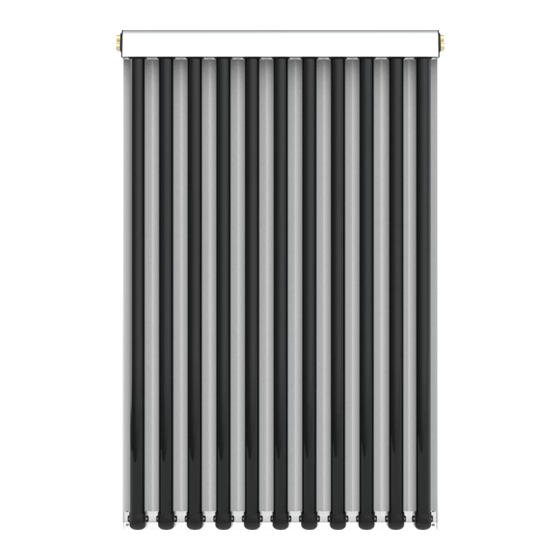
INFORMATION DESCRIPTION The panels with X-RAY R tubes have three main pre-assembled components: Vacuum tubes; Curved CPC mirrors; A collector with a heat distribution unit and integrated return tubing Each vacuum tube is composed of two concentric glass tubes; every single tube is closed at one end by a hemisphere, and is connected with another tube at the other end. - Page 10 TECHNICAL DATA modelli X-RAY R 10 R X-RAY R 11 R X-RAY R 12 R X-RAY R 13 R X-RAY R 14 R X-RAY R 15 R TECHNICAL DATA Evacuated tubes [ N ] Measurements [ mm ] 1106 x 1921 x 114 1216 x 1921 x 114 1326 x 1921 x 114 1436 x 1921 x 114...
- Page 11 modelli X-RAY R 16 R X-RAY R 17 R X-RAY R 18 R X-RAY R 19 R X-RAY R 20 R X-RAY R 21 R TECHNICAL DATA Evacuated tubes [ N ] Measurements [ mm ] 1766 x 1921 x 114 1876 x 1921 x 114 1986 x 1921 x 114 2096 x 1921 x 114...
-
Page 12: Bracket Types
TYPES OF BRACKETS Different types of X-RAY R manifolds are available to satisfy the different installation conditions. Whatever the type of fixture, follow the instructions for the chosen anchoring and continue to the paragraph “completion of the fixture system” which is common to all the solutions proposed below. For the distances of the anchoring points, see the pages indicated below according to the type of brackets, both for a sloping roof or a flat roof. -
Page 13: Sloping Roof (Track System)
TRACK SYSTEM (PARALLEL) SLOPING ROOF BRACKET SYSTEM FOR TILES ROOFING For distance between anchorage points see page 20. On completion of point proceed with instructions on page 23 SET BASE ASSEMBLY SEQUENCE 20 Nm 10 Nm Technical manual – Installation instructions and start-up X-RAY R - ver. 1.0 del 07/11/2018... -
Page 14: Flat Roof (Track System)
SLOPING ROOF BRACKET SYSTEM FOR ROOFING SHINGLES For distance between anchorage points see page 20. On completion of point proceed with instructions on page 23 SET BASE ASSEMBLY SEQUENCE 20 Nm H=100÷190 mm MIN 65mm 10 Nm Technical manual – Installation instructions and start-up X-RAY R - ver. 1.0 del 07/11/2018... - Page 15 SLOPING ROOF SCREW FASTENING SYSTEM For distance between anchorage points see page 20. On completion of point proceed with instructions on page 23 SET BASE ASSEMBLY SEQUENCE 12x300 (M12) MAX 200 mm MIN 40 mm X 12 X 12 MIN 100 mm ALTERNATIVA 10 Nm Technical manual –...
- Page 16 SLOPING ROOF CORRUGATED METAL SHEETING For distance between anchorage points see page 20. On completion of point proceed with instructions on page 23 SET BASE X 14 ASSEMBLY SEQUENCE 20 Nm 20 Nm 20 Nm Technical manual – Installation instructions and start-up X-RAY R - ver. 1.0 del 07/11/2018...
- Page 17 SLOPING ROOF STADING SEAM For distance between anchorage points see page 20. On completion of point proceed with instructions on page 23 SET BASE SEQUENZA DI MONTAGGIO ASSEMBLY SEQUENCE 20 Nm 10 Nm Technical manual – Installation instructions and start-up X-RAY R - ver. 1.0 del 07/11/2018...
- Page 18 FLAT ROOF TRIANGULAR STRUCTURE SYSTEM SET BASE SET BASE 35 x 25 x 1100 mm ASSEMBLY SEQUENCE > 15 Nm 15 Nm β n° Ø H mm 35° X = 100 Y = 100 A = 1 B = 1 1060 40°...
- Page 19 For distance between anchorage points see page 20. On completion of previous point proceed with instructions on page 23. 20 Nm 20 Nm 55 mm OPTIONAL MATERIAL Tension wires may be installed to ensure more structural stability under extreme windy conditions. >...
-
Page 20: Distance Between Anchorage Points
DISTANCE BETWEEN ANCHORAGE POINTS SLOPING ROOF – FLAT ROOF Each X-RAY R manifold must be installed on four fixing points and then use a fixing kit base for each manifold. For positioning see the figure below. Measurements are expressed in millimeters. MAXIMUM NUMBER OF INSTALLATION FOR STRINGS modello X-RAY 10 R... - Page 21 X-RAY X-RAY X-RAY X-RAY X-RAY X-RAY X-RAY X-RAY NUM. MASSIMO PANNELLI PUNTI DI FISSAGGIO ± 100 1206 1206 X-RAY X-RAY X-RAY X-RAY X-RAY X-RAY X-RAY NUM. MASSIMO PANNELLI PUNTI DI FISSAGGIO ± 100 1316 1316 X-RAY X-RAY X-RAY X-RAY X-RAY X-RAY NUM.
- Page 22 X-RAY X-RAY X-RAY X-RAY X-RAY NUM. MASSIMO PANNELLI PUNTI DI FISSAGGIO ± 100 1866 1866 X-RAY X-RAY X-RAY X-RAY X-RAY NUM. MASSIMO PANNELLI PUNTI DI FISSAGGIO ± 100 1976 1976 X-RAY X-RAY X-RAY X-RAY NUM. MASSIMO PANNELLI PUNTI DI FISSAGGIO ± 100 2086 2086 X-RAY...
-
Page 23: Completing Bracket System
COMPLETING BRACKET SYSTEM Once the roof fixing system is installed, whatever the type chosen, it is necessary to complete the installation with the appropriate parallel profiles (shown below). The assembly of the parallel profiles will be used to install the solar collectors. ASSEMBLY SEQUENCE Material supplied for each fixing system depending on the model chosen... -
Page 24: Easy System (Vertical)
EASY SYSTEM (VERTICAL) With the EASY system the following components are supplied, depending on the number of panels to be installed: BASE KIT EXTENSION KIT 1/2 BASE KIT KIT BASE KIT ESTENSIONE 1/2 KIT BASE 1 9 7 0 1 9 7 0 1 9 7 0 M8x20 M8x20... -
Page 25: Sloping Roof (Vertical)
M8x20 M8x20 M8x25 M8x30 M8x45 M8x25 M8x25 cod. 12345678 cod. 12345678 M8x75 M8x75 SLOPING ROOF M8x20 SCREW FASTENING SYSTEM ASSEMBLY SEQUENCE FOR INSTALLATION OF BASE KIT: M8x20 M8x20 TYPES OF ANCHORAGE SCREW KIT SHINGLES HOOK KIT TILES HOOK KIT KIT VITE KIT GANCIO DOPPIO KIT GANCIO TEGOLA KIT TUBO... - Page 26 ASSEMBLY SEQUENCE FOR INSTALLATION OF EXTENSION KIT: M8x45 M8x45 Technical manual – Installation instructions and start-up X-RAY R - ver. 1.0 del 07/11/2018...
-
Page 27: Distance Between Anchorage Points (Vertical)
DISTANCE BETWEEN ANCHORAGE POINTS VALID FOR COLLECTORS: BASE KIT EXTENSION KIT Technical manual – Installation instructions and start-up X-RAY R - ver. 1.0 del 07/11/2018... - Page 28 VALID FOR COLLECTORS: Technical manual – Installation instructions and start-up X-RAY R - ver. 1.0 del 07/11/2018...
-
Page 29: Flat Roof (Vertical)
FLAT ROOF EASY SYSTEM BASE KIT EXTENSION KIT KIT BASE KIT ESTENSIONE 1 bis 1/2 KIT BASE 1 9 7 0 1 9 7 0 1 9 7 0 M8x20 M8x20 M8x25 M8x30 M8x45 M8x25 M8x25 KIT BASE TETTO PIANO KIT ESTENSIONE T.PIANO M8x75 M8x75... - Page 30 MODIFICATION OF INCLINAZIOINE FLAT ROOF BRACKET 30° 35° 30° 35° 60mm - 3°Ø 60mm - 3°Ø 60mm - 3°Ø 60mm - 3°Ø 45° 40° 45° 40° 60mm - 3°Ø 510mm - 21°Ø 60mm - 3°Ø 510mm - 21°Ø COMPLETING BRACKET SYSTEM 75mm 75mm 75mm...
-
Page 31: Completing Bracket System (Vertical)
COMPLETING BRACKET SYSTEM M8x25 Technical manual – Installation instructions and start-up X-RAY R - ver. 1.0 del 07/11/2018... - Page 32 55mm 55mm 55mm M8x25 M8x25 M8x25 TO FIX TO FIX TO FIX 55mm M8x30 M8x30 M8x30 M8x25 TO FIX 55mm M8x30 M8x25 TO FIX Technical manual – Installation instructions and start-up X-RAY R - ver. 1.0 del 07/11/2018...
-
Page 33: Installation On Flat Roof With Ballast
INSTALLATION ON FLAT ROOF WITH BALLAST If it is not possible to fix the flat roof brackets onto the surface chosen for installation, anchorage can be achieved by the use of cement slabs (each corner 2 must be anchored to said slabs which must weigh at least 75 kg each, with dimensions of 30x20x55 cm). -
Page 34: Overall Dimensions
2,3 m 2,8 m β β α 1,5 m 2,2 m QUOTA Pleion X-RAY R B 30° B 45° Tabella quota a - misure espresse in millimetri NUMERO PANNELLI X-RAY 10 R X-RAY 11 R X-RAY 12 R X-RAY 13 R... -
Page 35: Hydraulic Connection
HYDRAULIC CONNECTION COLLECTORS CONNECTION The next chapter gives indicative information for the sizing of the water pipes to be connected to the panels. However, the correct sizing must always be calculated by the engineer appointed to plan the specific system in question. Metallic tubes that are suitable for contact with glycol solutions and high temperatures must be used. - Page 36 COLLECTORS POSITIONED ON MULTIPLE STRINGS Num. pannelli Gross Area 23,32 25,44 27,56 29,68 31,80 33,92 36,04 38,16 40,28 42,40 X-RAY Flow 16,50 18,00 19,50 21,00 22,50 24,00 25,50 27,00 28,50 30,00 10 R COPPER Diameter Ø 28/25 Ø 28/25 Ø 28/25 Ø...
-
Page 37: Pressure Drop
FLOW RATE OF THE HEAT TRANSFER FLUID To guarantee the correct operation of the solar system, a specific nominal flow rate of the heat transfer fluid must be guar- anteed of 9 l / h m2 per pipe installed. Example: •... -
Page 38: Pumbling Connections
PUMBLING CONNECTIONS The special feature of the X-RAY R collectors is that they can have a third integrated tube. This allows for choosing the basic standard model of the system. The head of an X-RAY R collector has hydraulic connections on each side, marked by dots in relief (see the figure on the right). - Page 39 RIGHT SIDE CONNECTION Connect the pipes from the boiler room on the right side of the collector series. Connect the return pipes (cold side) to the upper pipe connector on first collector (first/highest on the right). Blank the central pipe connector and connect the delivery pipe (hot side) to the lowest pipe connector.
- Page 40 LARGE SYSTEM For larger systems with for example more than 6 X-RAY 15 collectors, they can be arranged in two rows. Care must be taken to balance the system by making a connection between the two series. Attention: both rows must have the same number of collectors (see diagram). Alternatively, connect the collectors to several parallel rows, making the hydraulic connections in a balanced manner, as shown below.
- Page 41 COLLECTOR X-RAY R BASIC WITHOUT THIRD INTEGRATED PIPE AND PARALLEL DISTRIBUTION The X-RAY R solar collector has the third pipe completely integrated in the head and three lateral hydraulic connections that allow the hydraulic distribution in parallel on each module of the string. The collector also has probe holders on both sides to make the connection of the external pipes reversible, both from the right and from the left.
- Page 42 LEFT SIDE CONNECTION Connect the adduction pipe coming from the thermal plant on the left side of the collector battery. Connect the return pipe (cold side) to the top fitting of the first manifold (the first from the left), plug the central fitting and connect the delivery (hot side) to the low fitting.
- Page 43 Alternatively, connect the collectors to several parallel rows, making the hydraulic connections in a balanced manner, as shown below. It is advisable to provide for the arrangement of several probes, on the respective collector strings, in > order to interchange them in the event of a fault and to be able to check the correct balancing of the circuit in conditions operational.
-
Page 44: Warranty And Conditions
SYSTEM USER’S INSTRUCTIONS Normal functioning (with fabric sheets or with a cover made from its cardboard After a solar XRAY R solar panel system has been started up packaging), firmly fixed to the solar panel with belts or bands. by a specialised installer, the user does not need any special When the system has to be re-started after a long absence, it technical know-how. -
Page 45: Maintenance
REPAIRS Replacement of single tubes Removal of the tubes Materials and equipment required: 5 mm hexagonal Allen If the tube has sustained obvious damage, carefully remove wrench, bucket and broom to collect residues, and replacement the glass fragments without damaging the surface of the CPC tubes. - Page 46 FINAL NOTES Forced circulation X-RAY R solar collectors are perfectly of persons, animals or property. constructed as regards safety, in conformity with the provisions The products that fall within the field of application of the EC of the laws in force. directives comply with the essential requisites of said directives.
- Page 47 Technical manual – Installation instructions and start-up X-RAY R - ver. 1.0 del 07/11/2018...
- Page 48 Via Venezia, 11 - CEREA Verona infoline +39 0442 320295 info@pleion.it Pleion Srl si riserva il diritto di apportare modifiche di natura tecnica, estetica e commerciale senza alcun obbligo di preavviso. Versione 1.1 del 12/05/2014 Cod. 1020991200 Technical manual – Installation instructions and start-up X-RAY R - ver. 1.0 del 07/11/2018...
Need help?
Do you have a question about the X-RAY R Series and is the answer not in the manual?
Questions and answers