Table of Contents
Advertisement
Thank you for choosing CDI-SPD series photovoltaic water pump driver
produced by Delixi (Hangzhou) Inverter Co., Ltd.
Before using CDI-SPD series photovoltaic water pump driver (hereinafter
referred to as "the Product"), please read the manual carefully in order to ensure the
proper use. Improper use may result in the equipment's abnormal operation,
malfunction, decrease of service life and even personal injury accident. Therefore,
please do read the manual carefully before use and use the Product strictly according
to the manual. The manual is a standard file which must be kept properly after
reading for further repairing and maintenance of the Product in the future.
Besides the operating instructions, the manual also provides wiring diagram for
your reference. If having difficulties or special requirements for usage of the
Product, please feel free to contact our local offices or dealers or call our customer
service center of the headquarters directly. We will offer dedicated service to you.
We may change the contents of this Manual without a prior notice.
Please confirm the followings seriously when unpacking the Product:
1. Check if the Product is damaged, components and parts are damaged and
drop and the body is collided in the transportation process.
2. Check if the rated value labeled on the nameplate of the Product accords with
your order requirements and if the packaging box contains the machine that you
order, product certificate, operation manual and warranty card.
We are strict in the manufacture, packaging and delivery. For any inspection
omissions, please contact us or your supplier to solve the problem.
Foreword
Foreword
I
Advertisement
Table of Contents

Summary of Contents for Delixi CDI-SPD Series
- Page 1 Foreword Foreword Thank you for choosing CDI-SPD series photovoltaic water pump driver produced by Delixi (Hangzhou) Inverter Co., Ltd. Before using CDI-SPD series photovoltaic water pump driver (hereinafter referred to as “the Product”), please read the manual carefully in order to ensure the proper use.
-
Page 2: Table Of Contents
Table of Contents Table of Contents Foreword……………………………………………………………………………...I Chapter I Safety Operation and Attentions ..............1 1.1 Acceptance ....................1 1.2 Safety Operation Attentions ............... 2 Chapter II Product Information ..................3 2.1 Nameplate Data and Naming Rule ............. 3 2.2 Product Specification ................. 4 2.3 Product List .................... -
Page 4: Chapter I Safety Operation And Attentions
Chapter I Safety Operation and Attentions Chapter I Safety Operation and Attentions Please read this manual carefully before installation, operation, maintenance and inspection of the Product. Please read this chapter before using the Product in order to ensure personal, equipment and property safety. Attentions related to safety operation in the manual are classified into “warning”... -
Page 5: Safety Operation Attentions
Chapter I Safety Operation and Attentions 1.2 Safety Operation Attentions 1. Installation and maintenance should be performed by professional only. 2. Verify that rated voltage of the frequency inverter should conform with voltage level of AC power supply. Otherwise it shall cause hurt to human body or fire accident. -
Page 6: Chapter Ii Product Information
AC 1PH 220V±15% 50/60Hz Output:AC 3PH 0V~Uinput 0~400Hz 7.0A 1.5kW Hardware Version:1.1.00 Software Version:1.01.31 SPDG1R5S219K000001 CDI SPD G 1R5 S2 DELIXI inverter Product series no. Voltage Level (Rated Voltage) SPD Series SS2:1 PH AC 220V(Input/Output),50/60Hz DC:200~400V Product type S2:1 PH AC 220V,50/60Hz,DC:200~400V G:General Type T2:3 PH AC 220V,50/60Hz,DC:200~400V... -
Page 7: Product Specification
Chapter II Product Information 2.2 Product Specification -SS2 Machine Type -T2 Product -T4 Product Product Product 220(± 15%) 220(± 15%) 380(± 15%) AC input voltage (V) (1PH) (3PH) (3PH) Max. DC voltage (V) Starting voltage (V) Min. working voltage (V) Range of DC input voltage recommended 200~400... -
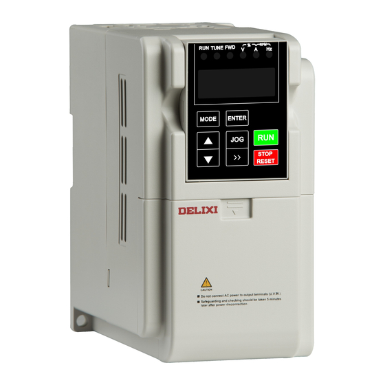
Page 8: Appearance And Installation Dimension
Chapter II Product Information Please specify the corresponding model and specification of the products when placing an order. For any special requirements, please contact us for negotiation. 2.4 Appearance and Installation Dimension Page 5... - Page 9 Chapter II Product Information Page 6...
- Page 10 Chapter II Product Information Page 7...
- Page 11 Chapter II Product Information Page 8...
-
Page 12: Daily Maintenance And Repairing
Chapter II Product Information 2.5 Daily Maintenance and Repairing (1) Daily maintenance The influence such as environmental temperature, humidity, dust and vibration may result in aging of the internal components of frequency inverter,which should cause potential fault of frequency inverter or reduction of its service life. Therefore, it is necessary to perform dailymaintenance andregular inspection with the frequency inverter. - Page 13 Chapter II Product Information storing it: A Please store it in original package as much as possible. B Long term storage should cause aging of electrolytic capacitor. Make sure to electrifyit once every half a year for at least 5 hours and to raise voltage to rated value slowly via voltage regulator.
-
Page 14: Chapter Iii Installation And Wiring
Chapter Ⅲ Installation and Wiring Chapter III Installation and Wiring 3.1 Installation Site and Space Installation site: 1. Avoid direct sunlight and outdoor direct use. 2. Don’t use it under corrosive gas and liquid environment. 3. Don’t use it under oil fog and splashing water environment. 4. - Page 15 Chapter Ⅲ Installation and Wiring Installation space: When frequency inverters are installed vertically, enough heat dissipation space shall be reserved in order to ensure effective cooling. Air outlet Air outlet Larger than 150 mm outlet Larger than Air inlet 150 mm inlet Installation Space of Frequency Inverter 1.
-
Page 16: Standard Wiring
Chapter Ⅲ Installation and Wiring 3.2 Standard Wiring See the standard wiring diagram of the main circuit and control circuit of the Product in the figure below: Gravity circuit breaker Q1 (DC+) PV input (DC-) Water pump CDI-SPD frequency inverter AC circuit breaker Q2 (R)... -
Page 17: Description Of The Terminals Of Frequency Inverter
Chapter Ⅲ Installation and Wiring 3.2.1 Description of the terminals of frequency inverter Description of the Main Circuit Terminals of Frequency Inverter: Identification Function Description Name R, S, T AC input 3-phase (single-phase) AC input terminal, (L1, L2) connected to power grid DC+, DC- PV DC input Input terminal of PV cell panel... - Page 18 Chapter Ⅲ Installation and Wiring U1 and V1 are the common terminals of the windings. Connect them to the output terminal W of the solar pumping inverter. Connect U2 to the output terminal U of the inverter. Connect V2 to the output terminal V of the inverter. (Note: Use the screws equipped with the inverter.) Now F28.39=1.
-
Page 19: Wiring Reference For The Main Circuit And Control Circuit Is As Shown In The Table Below
Chapter Ⅲ Installation and Wiring 3.2.2 Wiring reference for the main circuit and control circuit is as shown in the table below Model of Frequency Wire Gauge of Main Circuit (mm Wire Gauge of Main Inverter DC+/DC-, R/S/T, U/V/W Circuit (mm CDI-SPDG0R4SS2 CDI-SPDG0R7SS2 CDI-SPDG1R5SS2... -
Page 20: Earthing
Chapter Ⅲ Installation and Wiring 3.3 Earthing 1. Earthing resistance: 200 V level: 100 Ω or below 400 V level: 10 Ω or below 2. Don’t earth frequency Inverter, electric welder, motor or other large-current electrical equipment commonly. Make sure all earth wires inside conduit are laid separately from the leads of large-current electrical equipment. -
Page 21: Chapter Iv Keyboard Operation And Running
Chapter IV Keyboard Operation and Running Chapter IV Keyboard Operation and Running 4.1 Selection of Operation Mode The Product is provided with three control modes, including keyboard running, terminal running and self-running upon power-up. Users can select corresponding control mode according to field environment and working needs. See 5.1 for specific selections. -
Page 22: Keyboard Operation Method
Chapter IV Keyboard Operation and Running 4.3 Keyboard Operation Method 4.3.1 Keys and functions of keyboard (1) Keys and functions of keyboard Name Description Light off means the frequency inverter runs forward; light means the frequency inverter runs backward. Status frequency inverter is running when it is on indicato Keyboard start: TUNE light normally off... - Page 23 Chapter IV Keyboard Operation and Running (2) Keyboard 1: Keyboard dimensions: 65 mm*50 mm Keyboard seat installation dimensions: 77.5*59 mm Keyboard seat dimensions: 83.5*65 mm Keyboard 3 is the standard configuration for frequency inverter model 1~4 (3) Keyboard 2: Keyboard dimensions: 63 mm*75 mm Keyboard seat installation dimensions:99*70mm Keyboard seat dimensions:107*80mm Keyboard 3 is the standard configuration for...
-
Page 24: Methods To View/Give Parameters (With Digital Keyboard)
Chapter IV Keyboard Operation and Running 4.3.2 Methods to view/give parameters (with digital keyboard) 运行/停机监视方式 Running/power-off monitoring mode E.g.: Below is the example of modifying the 例:以下是启动等待时间参数P28.03 parameter 的值从1改到2的例子 Press MODE key once,then to 按MODE键1次,到参数设置 F28.03 of start waiting time from 1 to 2 parameter setting mode, Display 方式,如键盘显示代码P28.00 Display... -
Page 25: Keyboard Monitoring Data
Chapter IV Keyboard Operation and Running 4.3.3 Keyboard monitoring data When inverter waiting, keypad will show in turn Solar panel DC voltage Biggest frequency Output current When inverter running, keypad will show in turn Solar panel DC voltage Output frequency Output current When the parameter is displayed in cycle on power-off display interface and operation display interface, press... -
Page 26: Chapter V Functional Parameters Table
Chapter V Functional Parameters Table Chapter V Functional Parameters Table Description of functional parameters table: 1. The Product’s functional code, F28 Group, contains several subgroups. Within each subgroup, there are several functional codes the value of which can be set as different values. 2. -
Page 27: Basic Functions Of F28 Group
Chapter V Functional Parameters Table 5.1 Basic Functions of F28 Group Functional Modification Name Given Range Factory Default Code Restrictions ● F28.00 Software ver. 0: keyboard start: 1: auto start ☆ F28.01 Starting mode 2: terminal start 3:Reserved 0: MPPT mode 1: CVT mode ★... - Page 28 Chapter V Functional Parameters Table Functional Modification Name Given Range Factory Default Code Restrictions ☆ F28.16 CVT voltage 0-1000V Voltage of ☆ F28.17 0-1000V debugging mode Rated power of ● F28.18 Model motor Rated voltage of ● F28.19 Model motor Rated current of ●...
- Page 29 Chapter V Functional Parameters Table F28.02: Operation Mode 0. In MPPT mode, the frequency inverter turns power down and frequency reduction function; its final voltage upon start tracks from 80% open-circuit voltage, and the efficiency is above 98%. When luminous energy is adequate and table, the output frequency fluctuates within 1 Hz.
-
Page 30: Chapter Vi Troubleshooting
Chapter VI Troubleshooting Chapter VI Troubleshooting Failure Description Detail Troubleshooting U phase protection of Too fast acceleration; Damage OUt1 inverter unit of IGBT; Mis-operation Increase acceleration time; replace V phase protection of caused by inference; Poor power unit; Inspect the driving line; OUt2 inverter unit connection of driving line;... - Page 31 Chapter VI Troubleshooting Failure Description Details Troubleshooting Overheat Blocked air duct or damaged Dredge the air duct or replace the fan; rectification module fan; Environmental Reduces environmental temperature temperature too high; for overheat fault of OH2 inverter Overheat of inverter Over-load operation too long module module;...
- Page 32 Chapter VI Troubleshooting If the user sets water fullness alarm function; the equipment will shut down automatically when the warning Water fullness Full reservoir is on for a certain period of time, and A-tF warning the user needs not to notice it; otherwise, please check...
-
Page 33: Appendix 1 Recommended Configuration Of Solar Cell Modules
Appendix 1 Recommenden Configuration of Solar Cell Modules Appendix 1 Recommended Configuration of Solar Cell Modules Open-circuit Voltage Class of Solar Cell Module 37± 1V 45± 1V Product Model Number of each Number of each Module power ± 5 string of modules * Module Power string of modules * number of strings...
Need help?
Do you have a question about the CDI-SPD Series and is the answer not in the manual?
Questions and answers