
Summary of Contents for Obvius A8911-23
- Page 1 A8911-23 Modbus Pulse Input Module Obvius, LLC Installation and Operation Manual Date Nov 3, 2011 Page 1 A8911-23 1.800.561.8187 information@itm.com www. .com...
- Page 2 Obvius's authorized facilities; (4) has not been sold subject to other warranty terms specified at the time of sale; and (5) is still owned by the original purchaser. This warranty provides specific legal rights that may be varied by state law. Obvius's products are not designed for life or safety applications.
-
Page 3: Table Of Contents
Operation.....................................6 Troubleshooting...................................7 Register Listing..................................7 Register Functions..................................9 A8911-23 Firmware Update..............................10 Mechanical Drawings................................11 Markings and Symbols: WARNING: A potential risk exists if the operating instructions are not followed General Warning Symbol: This symbol indicates the need to consult the operating instructions provided with the product. -
Page 4: Overview
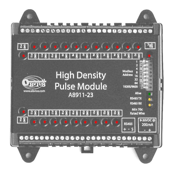
The A8911-23 is designed for pulse counting applications where large number of pulse output devices need to be connected to a Modbus network. The A8911-23 will count contact closures on 23 separate inputs and store the totalized pulse count internally using non-volatile memory. The pulse count totals are then read using the RS485/Modbus protocol. Applications include reading gas/water/electric meters in common building areas for energy information and reporting purposes. -
Page 5: Electrical Connections
3) Turn on the power supply. Confirm the green Alive LED starts blinking. Turn off the power to the module. 4) Attach the RS485 +, - and shield wires to the A8911-23 module. Attach the other end of the RS485 line to the Modbus master device, such as an AcquiSuite. -
Page 6: Configuration
- If the A8911-23 receives any Modbus traffic on the RS485 port, the yellow RX led should blink. - If the A8911-23 receives a Modbus query that is addressed to it specifically, the yellow TX LED should blink and it will respond to the query. -
Page 7: Troubleshooting
Verify the pulse output device is operating. Disconnect the A8911-23 input and use a hand held digital meter and measure resistance of the pulse output device. Verify that the pulse output device is operational and the contact closure reads less than 1000 ohms when closed. For high resistance pulse devices such as intrinsic barriers, the “contact closure threshold”... - Page 8 RS485 baud rate. 2=9600, 3=19200. 1020 41021 UINT16 reason for reboot. 0x01=POR, 0x02=EXTR 0x04=WDTR 0x08=BODR, 0x8000=WDTOF Modbus function 0x11 Slave ID response will report the following: "Obvius, A8911-23, pulse counter, 23 channel", id=47 Page 8 A8911-23 1.800.561.8187 information@itm.com www. .com...
-
Page 9: Register Functions
Next the Master reads the second (LSW) register and gets 0x0000. When the two registers are combined, the result is 0x00000000. The proper way to handle this situation is to simply read both registers in a single Modbus query. Page 9 A8911-23 1.800.561.8187 information@itm.com www. -
Page 10: A8911-23 Firmware Update
WARNING: Disconnect power and lock-out all power sources during installation. DO NOT CONNECT RS232 PORT WITH CURRENT INPUTS LIVE Step 3: Remove the plastic lid from the A8911-23 module. The plastic lid is held in place with two plastic clips, one on each side. -
Page 11: Mechanical Drawings
Mechanical Drawings DIN-Rail (EN50022) mount package: Width 105mm (6 modules) 3.39in 86mm 1 2 3 4 5 6 7 8 +24V Shield 485 - 485 + A8911-23 Rev B 3.875 in Mounting holes Page 11 A8911-23 1.800.561.8187 information@itm.com www. .com...
Need help?
Do you have a question about the A8911-23 and is the answer not in the manual?
Questions and answers