Table of Contents
Advertisement
Quick Links
Advertisement
Table of Contents
Troubleshooting

Summary of Contents for UTICOR TOUGH UT3 Series
- Page 1 UT3/Touch Plus Manual...
-
Page 2: Table Of Contents
UT3 Series Table of contents Warnings ........................3 Product Overview ......................4 Specifications ......................... 5 Installation Considerations ..................... 6 Safety Considerations ....................6 Installation Considerations ..................7 Electrical Considerations ..................... 8 Shielding from RFI ...................... 9 Installation ........................11 Mounting Information ....................11 Powering the Unit ..................... -
Page 3: Warnings
Consult PLC Editor Programming Software Help. You may also find answers to your questions in the operator interface section of our website info@uticor.com If you still need assistance, please call our technical support at 61-9482 4000 or FAX us at 61-9482 4222. -
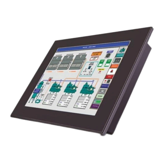
Page 4: Product Overview
UT3 Series Product Overview Thank You for using Uticor's new line of stunning HMIs - the UT3 Series. As the latest in a long line of high preforming and easy programming HMIs, the UT3 Series is both convenient and fast to use. In addition, the UT3 Series provides several enhancements over its predecessors including additional communication ports, higher resolution, a standard MicroSD slot, and built in remote monitoring and control features. -
Page 5: Specifications
Uticor Tough UT3 Series UTICOR TOUGH UT3 SERIES 6, 8 and 10-inch Model Specifications Part Number UT3-06TC-0-A-PV700-0 UT3-08TC-0-A-0-0 UT3-10TC-0-A-0-0 Specification 6” TFT Color Slim Bezel 8” TFT Color Slim Bezel 10” TFT Color Slim Bezel Enclosure NEMA 4, 4X (Indoor/Outdoor) Class I, Div II Display Type 6”... - Page 6 Uticor Tough UT3 Series UTICOR TOUGH SUNLIGHT READABLE SERIES 6 and 10-inch Model Specifications Part Number UT3-06TC-0-A-PV700-SUN UTTP-10TC-0-A-0-SUN Specification 6” TFT Color Slim Bezel 10” TFT Color Slim Bezel Enclosure NEMA 4, 4X (Indoor/Outdoor) Class I, Div II Display Type 6”...
-
Page 7: Installation Considerations
UT3 Series Safety Considerations Please follow all applicable local and national codes to ensure maximum safety of the equipment and personnel. The installation and operational environment must be maintained per the latest revision of these codes. You are responsible to determine the codes to be followed and to verify the compliance of equipment, installation, and operation with the latest revision of these codes. -
Page 8: Installation Considerations
UT3 Series Installation Considerations Our products have been designed and tested for operation in the most demanding industrial environments. Modern solid-state industrial controls are complex electronic equipment that operate at low levels of voltage and current, co-existing with components that operate at much higher levels of power. The difference in operating power characteristics between the high and low power control devices creates the possibility of unwanted signals being generated, thus causing interference. -
Page 9: Electrical Considerations
UT3 Series controls (motors, starters, solenoids, etc.) should be housed separately or at the farthest point when enclosed within the cabinet. We recommend that the unit has a minimum clear space of 2" on all sides for adequate ventilation as shown in the image on the right. Electrical Considerations This section is designed to provide you with a very basic understanding of electrical noise and how to keep it away from CPUs. -
Page 10: Shielding From Rfi
UT3 Series Shielding from RFI Shielded Cables Power cables, I/O cables or wiring, and communication cables should all be separate so that they do not couple the conducted RFI on any of these wires/ cables. Another path for RFI into the PLC is through its RS232 port. Hence, the cables to this port must be shielded properly. - Page 11 UT3 Series Cabinet Wiring The wiring of the UT3 unit to the “field outside the cabinet must be by design. The wiring cannot be random in order to get the various points of the cabinet and the “field electrically connected. Below are some general rules that apply in most situations: o Provide a separate power source to electronic controls and keep this power bus away from any I/O power.
-
Page 12: Installation
UT3 Series Mounting Information Cutout Dimensions Units: inches [millimeters] UT3 Panel Dimensions Unit Size 6" 9.69" [246mm] 7.05" [179mm] 3.21" [81.66mm] 8" 10.79" [274mm] 8.50" [216mm] 3.13" [79.6mm] 10" 12.5" [317.5mm] 9.48" [241mm] 3.13" [79.6mm] Panel Cutout Dimensions Unit Size Depth 6"... - Page 13 UT3 Series Mounting Instructions Before mounting your UT3 Series unit, please verify you have the necessary items: · UT3 Series unit · 4 or 6 DIN clip assemblies (depending on model size) · a Phillips #1 screwdriver (or equivalent) When ready to proceed: Prepare the DIN clip assembly first by placing the nut on the screw.
- Page 14 UT3 Series 13 / 34...
-
Page 15: Powering The Unit
UT3 Series Powering the Unit Connect the power input wires into the HMI's power terminals. Supply 24VDC nominal (20- 30VDC) power to the system. If the unit does not power up correctly, remove power from the system and check all the wiring. In addition, see Indicator Light section... -
Page 16: Communication And Ports
UT3 Series Communication and Ports PLC Port This is the RS-232C, RS-422A or RS-485A female 15-pin D- Sub Connector to connect to other PLCs. Most PLCs connect to the 15-pin D-Sub with a cable specific to the PLC type. Connection Number Chassis GND PLC TXD (RS-232C) -
Page 17: Com1 Port
UT3 Series COM1 Port The UT3 Series has a built-in serial port (COM1 PORT) located on the 9-pin D-Sub connector. COM1 PORT is an RS-232 port which requires an appropriate RS-232C cable (P/N: UT-CPG1) for programming the unit through a PC. It serves as the default programming port on the UT3 Series. -
Page 18: Ethernet Port
The following is a list of current drivers supported by the UT3 Series units. We are always updating PLC compatibility, if you don't see your type PLC in this table, visit our web site at uticor.net or call technical support at 1-563-359-7501. PLC Manufacturer... -
Page 19: Micro Sd Slot
UT3 Series Micro SD slot A Micro SD slot is available to allow for additional storage or data transfer. Insert a Micro SD into the slot and it will load automatically. Additional details about using a MicroSD Card for data logging is available in the Data Logging Overview... -
Page 20: Programming The Panel
UT3 Series Programming the Panel Create a Project This section outlines the basics of creating a project using the uWIN software. Further programming information for the UT3 Series is located in the Software Manual. Launch your Programming Software and select how you would like the program to link to the Windows HMI unit. - Page 21 UT3 Series 3. Next, select the PLC Manufacturer and protocol you would like to use with the unit. (Example shown below.) 4. Click OK to launch the editing software program. The Main Project Window will then appear. The steps below outline how to create a sample panel program. Create a Panel Program: Click on “Panied and "Scr 1"...
- Page 22 UT3 Series Click anywhere on the screen to place the Button object. Double click the icon to open its object dialog box if you need to adjust the object's appearance or attributes. Clicking "Simulates Press" will allow you to toggle between On and Off states. Similarly, you can create an Indicator Light Object by selecting Objects >...
-
Page 23: Transfer A Project
UT3 Series Transfer a Project After a project is complete, the next step is to transfer the project to the UT3 Series unit. When editing projects online, programming information is automatically sent to the unit once the project is saved. When editing in an off-line mode, the project information will need to be transferred. -
Page 24: Data Logging Overview
UT3 Series Data Logging Overview The UT3 Panel offers a flexible Data Acquisition capability. You can acquire and save the data for one or more tags defined in the panel. The acquired data along with a time stamp is saved in CSV file format in the USB stick or the MicroSD card, depending on how the schedule is set. - Page 25 UT3 Series Click on Add/Elit buttn tt lispeaa tti ““ll “A Stiluei itaies.d The "Add DAQ Schedule Details" box will appears allowing you create a new schedule for the panel. Schedule names can be either be Tag based or a Constant (user defined name).
- Page 26 UT3 Series Types of Schedules Time based – at regular Intervals Allows you to store the tag value at regular time intervals, anywhere from every 1 second to every 1000 hours. Time based – at Specifc Times Allows you to store the value of a group of tags up to 10 specific times. You may always edit / delete a specified time.
- Page 27 UT3 Series Numeric Type event: Event Based - at Regular Intervals: Allows you to create an event and store the values of a group of tags on the occurrence of the same during a set time period. Based on the data type of the event tag, schedule can be either Discrete Event Type or Numeric Event Type.
- Page 28 UT3 Series Pausing Data Acquisition and Ejecting Card Pause / Resume Data Collection Tag: This is a discrete tag that can be controlled by user (e.g. through a Push Button) or by PLC to enable or disable data acquisition. When the tag's value is 0, data collection is enabled;...
- Page 29 UT3 Series Safe to Eject Card Tag: This is a discrete internal tag. The tag must not be mapped to PLC. The Panel would set this tag when it is safe to remove the card. It is reset whenever it is unsafe to remove the card.
-
Page 30: Maintenance And Troubleshooting
UT3 Series Maintenance and Troubleshooting Hardware Maintenance Routine maintenance checks should be performed on the unit to avoid any risk of hardware problems. The UT3 Seriesis designed to be a very rugged controller so that just a few checks periodically will help keep it up and running. The key points to be checked include: ·... -
Page 31: Changing The Battery
UT3 Series Changing the Battery The unit comes with a built in Lithium battery with a 5 year life expectancy. The steps below outline the process to change the battery inside the unit. Since only the information saved to the registers/discretes available on a power cycle will remain intact, please save pertinent information before attempting to change the battery. -
Page 32: Update Firmware
UT3 Series Update Firmware 1 Insert a RS-232C cable into the COM1 port and launch the uWin software. 2 Select Edit Program ON-LINE and enter a project name (e.g. Test). Click OK. 4 Next, select the PLC Manufacturer and protocol you would like to use with the unit. (Example shown below.) Then click OK. - Page 33 UT3 Series 32 / 34...
-
Page 34: Troubleshooting
If you encounter difficulties while using our UT3 Series device, please consult the table below. Additional assistance is also available within the uWIN Software Help. Alternatively, you may also find answers to your questions in the operator interface section of our website @ uticor.net. Problem Possible...
Need help?
Do you have a question about the TOUGH UT3 Series and is the answer not in the manual?
Questions and answers