
Related Manuals for Allied Telesis DNC10 Series

Summary of Contents for Allied Telesis DNC10 Series
- Page 1 DNC10 Series Single 10G Port Network Interface Cards with PCIe x4 Express Interface DNC10T DNC10LC DNC10SP Installation and User’s Guide 613-002857 Rev B...
- Page 2 Allied Telesis, Inc. has been advised of, known, or should have known, the...
- Page 3 Declaration of Conformity Manufacturer Name: Allied Telesis, Inc. Declares that the product: DNC10 Series 1 Port 10G Network Interface Card (w/PCI x4 Express Interface) Model Numbers: DNC10LC, DNC10SP, and DNC10T This equipment has been tested and found to comply with the limits for a Class B digital device, pursuant to Part 15 of FCC Rules.
- Page 4 RFI Emissions FCC Class B, EN55032 Class B, VCCI Class B, ICES-003 Issue 6 Immunity EN55035 Electrical Safety EN2368-1 (TUV), UL 62368-1 ( Laser Safety EN60825...
- Page 5 Translated Safety Statements Important: Safety statements that have the symbol are translated into multiple languages in the Translated Safety Statements document at www.alliedtelesis.com/library. Remarque: Les consignes de sécurité portant le symbole sont traduites dans plusieurs langues dans le document Translated Safety Statements, disponible à l'adresse www.alliedtelesis.com/ library.
-
Page 7: Table Of Contents
Contents Preface ................................13 Safety Symbols Used in this Document .....................14 Contacting Allied Telesis..........................15 Chapter 1: Introduction ..........................17 Functional Description..........................18 DNC10LC Fiber Optic Port.........................20 DNC10SP SFP+ Port..........................21 DNC10T Twisted Pair Copper Port ......................23 Features ..............................25 Hardware .............................25 Software ..............................25 Chapter 2: Installing the Hardware ......................27 System Requirements..........................28... - Page 8 Contents Jumbo Packet............................69 Large Send Offload v1 (IPv4) ........................71 Large Send Offload v2 (IPv4) ........................72 Large Send Offload v2 (IPv6) ........................73 Link Speed..............................74 Locally Administered Address ........................76 Log Link State Event ..........................78 Maximum Number of RSS Queues ......................79 NS Offload ..............................
- Page 9 Tables Table 1. DNC10 Series Network Interface Cards .......................19 Table 2. DNC10LC LED Status ............................20 Table 3. DNC10SP LED Status ............................22 Table 4. DNC10T Link and Activity LEDs ...........................24 Table 5. Weights ................................115 Table 6. Dimensions .................................115 Table 7. Environmental Specifications ..........................116 Table 8.
- Page 10 List of Tables...
- Page 11 Figure 17: Device Manager Window............................ 46 Figure 18: Searching for Device Manager ........................... 46 Figure 19: Selecting the DNC10 Series Adapter in the Device Manager ................48 Figure 20: Update Driver Software Window ........................49 Figure 21: Browse for Drivers on Your Computer........................ 49 Figure 22: Advanced Properties Window ..........................
- Page 12 List of Figures Figure 50: Wake from Power Off State Page........................99 Figure 51: Wake on Link Page............................101 Figure 52: Wake on Magic Packet Page..........................102 Figure 53: Wake on Pattern Match Page........................... 103 Figure 54: Wake on Ping Page ............................104 Figure 55: Device Manager Shortcut Menu ........................
-
Page 13: Preface
Series adapters. The Preface discusses the following topics: “Safety Symbols Used in this Document” on page 14 “Contacting Allied Telesis” on page 15 This guide contains the installation instructions for the following single 10G port Network Interface Cards (NICs). -
Page 14: Safety Symbols Used In This Document
Preface Safety Symbols Used in this Document This document uses the following conventions: Note Notes provide additional information. Caution Cautions inform you that performing or omitting a specific action may result in equipment damage or loss of data. Warning Warnings inform you that performing or omitting a specific action may result in bodily injury. -
Page 15: Contacting Allied Telesis
DNC10 Series Network Interface Card Installation and User’s Guide Contacting Allied Telesis If you need assistance with this product, you may contact Allied Telesis technical support by going to the Support & Services section of the Allied Telesis web site at www.alliedtelesis.com/support. You can find links for... - Page 16 Preface...
-
Page 17: Chapter 1: Introduction
Chapter 1 Introduction This chapter provides an introduction to the DNC10 Series network interface cards (NICs) with Wake-on-LAN (WoL). This chapter contains the following sections: “Functional Description” on page 18 “DNC10LC Fiber Optic Port” on page 20 “DNC10SP SFP+ Port” on page 21 ... -
Page 18: Functional Description
These cards have Peripheral Component Interconnect Express (PCIe) bus connectors. The DNC10 Series network adapters support the PCIe x4 v3.0, 2.1 and 1.1a compliant interfaces. The AT-DNC10 Series can perform accelerated Ethernet data networking and storage networking simultaneously for all popular protocols used in the data center, and includes features such as Data Center Bridging. -
Page 19: Table 1. Dnc10 Series Network Interface Cards
The maximum operating distance of the SFP+ port on the DNC10SP adapter depends on the transceiver. Refer to the product's data sheet on the Allied Telesis web site for a list of supported transceivers. After physically installing the DNC10 Series network adapter in your computer, install the driver software by referring to Chapter 3, “Installing... -
Page 20: Dnc10Lc Fiber Optic Port
Chapter 1: Introduction DNC10LC Fiber Optic Port The DNC10LC adapter card has one 10Gbps fiber optic port with a duplex LC connector. The port has a maximum operating distance of 300m with OM3 fiber optic cable. The DNC10LC links at 10G only. It has one LED to show the networking state. -
Page 21: Dnc10Sp Sfp+ Port
DNC10 Series Network Interface Cards Installation and User’s Guide DNC10SP SFP+ Port The DNC10SP adapter has an SFP+ port where you can plug in an SFP+ transceiver to connect the adapter to a compatible link partner. The DNC10SP will detect whether a 10G SFP+ or 1G SFP has been inserted and will only operate at that speed. -
Page 22: Table 3. Dnc10Sp Led Status
An SFP+ transceiver must be purchased separately. For a list of supported transceivers, refer to the product's data sheet on the Allied Telesis web site. The SFP+ port is shown in Figure 4. Figure 4. SFP+ Port on the DNC10SP Adapter Table 2 describes the link states that the LED indicates. -
Page 23: Dnc10T Twisted Pair Copper Port
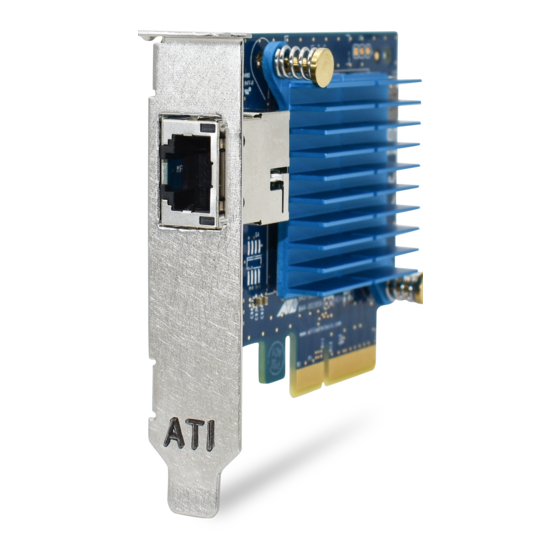
DNC10 Series Network Interface Cards Installation and User’s Guide DNC10T Twisted Pair Copper Port The DNC10T adapter card has one copper port that can operate at 100Mbps or 1/2.5/5/10Gbps. The card uses Auto-Negotiation to automatically set port speed and supports full-duplex mode only. The port has two status LEDs. -
Page 24: Table 4. Dnc10T Link And Activity Leds
Chapter 1: Introduction The LEDs for the twisted pair port are described in Table 4. Table 4. DNC10T Link and Activity LEDs Port LED State Network State LEDs Left Green Steady On The transceiver has established a 10G link to a remote device. Amber Steady On The transceiver has established a 100Mbps or 1/2.5/5G link to a remote... -
Page 25: Features
DNC10 Series Network Interface Cards Installation and User’s Guide Features Here are the key features of the DNC10 Series network interface cards: Hardware DNC10SP supports one SFP+ port DNC10LC supports one fiber optic port with a duplex LC connector port DNC10T supports one twisted pair port ... - Page 26 Chapter 1: Introduction...
-
Page 27: Chapter 2: Installing The Hardware
Chapter 2 Installing the Hardware This chapter contains the following sections: “System Requirements” on page 28 “Reviewing Safety Precautions” on page 29 “Pre-Installation Checklist” on page 31 “Replacing the Bracket” on page 32 “Installing a Network Adapter” on page 34 ... -
Page 28: System Requirements
Chapter 2: Installing the Hardware System Requirements Before installing the DNC10 series network adapter, make sure your system meets the requirements listed below: Computer with one of the following operating systems installed: – Windows 10, 64-bit – Windows Server 2016 –... -
Page 29: Reviewing Safety Precautions
DNC10 Series Network Interface Cards Installation and User’s Guide Reviewing Safety Precautions Important: Safety statements that have the symbol are translated into multiple languages in the Translated Safety Statements document at www.alliedtelesis.com/library. Remarque: Les consignes de sécurité portant le symbole sont traduites dans plusieurs langues dans le document Translated Safety Statements, disponible à... - Page 30 Chapter 2: Installing the Hardware Warning The module is being installed in a system that operates with voltages that can be lethal. Before you remove the cover of your system, you must observe the following precautions to protect yourself and to prevent damage to the system components. –...
-
Page 31: Pre-Installation Checklist
DNC10 Series Network Interface Cards Installation and User’s Guide Pre-Installation Checklist Before installing the DNC10 series network adapter, check the following list: 1. Check that your computer has an appropriate open PCIe slot. 2. Verify that your system is using the latest BIOS. -
Page 32: Replacing The Bracket
Chapter 2: Installing the Hardware Replacing the Bracket The DNC10 series network adapter is shipped with the low-profile bracket attached to the adapter. Additionally, a standard bracket is supplied also. Depending on your system, you may need to replace the bracket attached to your adapter card. -
Page 33: Figure 8: Fastening Screws Onto Standard Bracket
DNC10 Series Network Interface Cards Installation and User’s Guide Figure 8. Fastening Screws onto Standard Bracket... -
Page 34: Installing A Network Adapter
Chapter 2: Installing the Hardware Installing a Network Adapter The following instructions apply to installing a DNC10 series network adapter in most systems. Refer to the manuals that were supplied with your system for details about performing these tasks on your particular system. -
Page 35: Figure 9: Removing The Pc Cover
DNC10 Series Network Interface Cards Installation and User’s Guide Figure 9. Removing the PC Cover 3. Select an empty, non-shared PCIe slot and remove the faceplate. Keep the faceplate in a safe place. You may need it for future use. See Figure 10. -
Page 36: Figure 11: Inserting The Network Adapter
Chapter 2: Installing the Hardware Figure 11. Inserting the Network Adapter Caution Do not use excessive force when seating the adapter, as the force may damage the system or the adapter. If the adapter resists seating, remove it from the system, realign it, and try again. ... - Page 37 DNC10 Series Network Interface Cards Installation and User’s Guide 9. Power the system on. When the system returns to proper operation, the network adapter is fully installed. Next, connect the network cables. See “Connecting the Network Cable” on page 38.
-
Page 38: Connecting The Network Cable
Chapter 2: Installing the Hardware Connecting the Network Cable Depending on the type of DNC10 series network adapter installed, it is equipped with an SFP+, fiber optic, or copper RJ45 port. To connect the network adapter to the network, you must have a cable with the appropriate connector. -
Page 39: Dnc10T Twisted-Pair Copper Cable
DNC10 Series Network Interface Cards Installation and User’s Guide DNC10T To connect a copper network cable to the network adapter, perform the following procedure. Twisted-Pair Copper Cable 1. Prepare a twisted-pair copper cable. 2. Connect one end of the cable to the network adapter. - Page 40 Chapter 2: Installing the Hardware...
-
Page 41: Chapter 3: Installing The Driver Software
Chapter 3 Installing the Driver Software This chapter describes how to install driver software for the DNC10 Series network adapter onto your operating system. It contains the following topics: “Overview” on page 42 “Downloading the Driver Software” on page 43 ... -
Page 42: Overview
Chapter 3: Installing the Driver Software Overview After you install the DNC10 Series network adapter on your computer, your next step is to install the driver software onto your Windows operating system. You can install the driver software using the Device Manager or the silent installation method. -
Page 43: Downloading The Driver Software
DNC10 Series Network Interface Cards Installation and User’s Guide Downloading the Driver Software The driver software for the adapters is available on the Allied Telesis website. The driver is the same for all DNC10 Series NICs. To download the software: 1. -
Page 44: Figure 14: Login Window
Chapter 3: Installing the Driver Software 7. Enter the Login ID and Password and click Login. Figure 14. Login Window 8. Select the driver for the DNC10 Series network adapter and your operating system. 9. Save the zip folder onto your system. -
Page 45: Accessing The Device Manager
DNC10 Series Network Interface Cards Installation and User’s Guide Accessing the Device Manager When you install or update the driver software for DNC10 Series network adapter, you must first access the Device Manager. The procedures for accessing the Device Manager are slightly different among Windows operating systems. -
Page 46: Figure 17: Device Manager Window
Chapter 3: Installing the Driver Software The Device Manager window appears. Figure 17. Device Manager Window Option 2 Another option to accessing the Device Manager is: 1. Type Device Manager in the search field at the bottom left corner. The following screen appears. Figure 18. -
Page 47: Installing The Driver Software
DNC10 Series Network Interface Cards Installation and User’s Guide Installing the Driver Software Once you physically install the DNC10 Series network card, the system detects the new hardware and creates an entry in the Device Manager when the Windows operating system first boots up. Shortly after you log in, you need to install the driver software for your adapter card. -
Page 48: Figure 19: Selecting The Dnc10 Series Adapter In The Device Manager
Ethernet Controller, Aquantia device, or Allied Telesis device. The shortcut menu appears. See Figure 19 as an example. Figure 19. Selecting the DNC10 Series Adapter in the Device Manager b. Select Update Driver Software. The Update Driver Software window appears. See Figure 20 on... -
Page 49: Figure 20: Update Driver Software Window
DNC10 Series Network Interface Cards Installation and User’s Guide Figure 20. Update Driver Software Window c. Select Browse my computer for driver software. The Browse for Drivers on Your Computer window prompts you to enter the location of the driver folder. See Figure 21 as an example. - Page 50 Chapter 3: Installing the Driver Software A confirmation message appears when the driver software is successfully updated. 6. Click Close.
-
Page 51: Updating The Driver Software
Device Manager may list your adapter entry as an Ethernet Controller, Aquantia device, or Allied Telesis device. To update the driver software for your DNC10 Series network adapter, see “Installing the Driver Software” on page 47. -
Page 52: Performing The Silent Installation
Performing the Silent Installation To simplify the driver installation process, you may perform a silent installation when installing driver software for the DNC10 Series network adapter card entries. The silent installation is a method of installing software in the silent mode without constant interactions by suppressing dialog boxes. -
Page 53: Viewing Supported Dpinst Options
DNC10 Series Network Interface Cards Installation and User’s Guide 7. Change the directory to the folder where the utility and the dpinst driver files reside. 8. Install the driver in the silent mode by entering the following command: > dpinst /S... - Page 54 Chapter 3: Installing the Driver Software...
-
Page 55: Chapter 4: Modifying Advanced Properties
Chapter 4 Modifying Advanced Properties This chapter includes the following topics: “Overview” on page 57 “Accessing Advanced Properties” on page 58 “ARP Offload” on page 60 “Downshift Retries” on page 61 “Energy-Efficient Ethernet” on page 62 ... - Page 56 Chapter 4: Modifying Advanced Properties “Wake from Power Off State” on page 99 “Wake on Link” on page 101 “Wake on Magic Packet” on page 102 “Wake on Pattern Match” on page 103 “Wake on Ping” on page 104 ...
-
Page 57: Overview
DNC10 Series Network Interface Cards Installation and User’s Guide Overview The DNC10 series network adapters allow you to modify advanced properties to meet your requirements. To access the advanced properties, access Device Manager, then go to each advanced property page. -
Page 58: Accessing Advanced Properties
1. Access the Device Manager. See “Accessing the Device Manager” on page 45. 2. In the Device Manager window, click Network Adapters. 3. Double-click Allied Telesis AT-2911GP Series Ethernet. The properties window pops up. 4. Click the Advanced tab. The Advanced Properties window opens as shown in Figure 22. -
Page 59: Figure 22: Advanced Properties Window
DNC10 Series Network Interface Cards Installation and User’s Guide Figure 22. Advanced Properties Window... -
Page 60: Arp Offload
Chapter 4: Modifying Advanced Properties ARP Offload The ARP Offload feature enables the adapter not to wake up when responding to an ARP request. ARP is used to verify whether a computer is still present on the network and resolve an IP address into a MAC address. -
Page 61: Downshift Retries
DNC10 Series Network Interface Cards Installation and User’s Guide Downshift Retries This feature offers a way for the network systems to reliably select the best speed that the cabling plant can support. When `on`, it enables a link speed downgrade in case the currently selected speed is constantly failing. -
Page 62: Energy-Efficient Ethernet
Chapter 4: Modifying Advanced Properties Energy-Efficient Ethernet The Energy-Efficient Ethernet property allows you to optimize the energy usage of the interface over Ethernet. Note This feature is valid only for copper ports. To view the Energy-Efficient Ethernet feature, do the following: 1. -
Page 63: Flow Control
DNC10 Series Network Interface Cards Installation and User’s Guide Flow Control The Flow Control feature allows you to control the flow between the DNC10 adapter port and its link partner. You can enable or disable the adapter port to process received PAUSE frames and transmit PAUSE frames. - Page 64 Chapter 4: Modifying Advanced Properties 4. Click OK.
-
Page 65: Interrupt Moderation
DNC10 Series Network Interface Cards Installation and User’s Guide Interrupt Moderation The Interrupt Moderation feature allows you to limit the rate of interrupts to the CPU during packet transmission and packet reception. When this feature is enabled, interrupts are handled as a group so that the CPU utilization decreases;... -
Page 66: Interrupt Moderation Rate
Chapter 4: Modifying Advanced Properties Interrupt Moderation Rate To improve system performance, you can configure the interrupt moderation rate. This setting defines the maximum number of interrupts per second that the adapter is allowed to generate. Note that decreasing this value decreases the CPU usage. To specify or change the Interrupt Moderation Rate feature, do the following: 1. - Page 67 DNC10 Series Network Interface Cards Installation and User’s Guide Medium — ITR = 950. Low — ITR = 400. Off — ITR = 0, no limit. 4. Click OK.
-
Page 68: Ipv4 Checksum Offload
Chapter 4: Modifying Advanced Properties IPv4 Checksum Offload To specify or change the IPv4 Checksum Offload feature, do the following: 1. Access the Advanced Properties. See “Accessing Advanced Properties” on page 58. 2. Select IPv4 Checksum Offload in the Property box. The IPv4 Checksum Offload page is displayed as shown in Figure 29. -
Page 69: Jumbo Packet
DNC10 Series Network Interface Cards Installation and User’s Guide Jumbo Packet Enables the network adapter to transmit and receive oversized Ethernet frames that are greater than 1500 bytes, but less than or equal to 16348 bytes in length. This property requires the presence of a switch that is able to process jumbo frames. - Page 70 Chapter 4: Modifying Advanced Properties Disabled — The adapter does not handle jumbo frames. 4. Click OK.
-
Page 71: Large Send Offload V1 (Ipv4)
DNC10 Series Network Interface Cards Installation and User’s Guide Large Send Offload v1 (IPv4) Normally, the TCP segmentation is done by the protocol stack. When you enable the Large Send Offload property, the TCP segmentation can be done by the network adapter. The default setting for this property is Enabled. -
Page 72: Large Send Offload V2 (Ipv4)
Chapter 4: Modifying Advanced Properties Large Send Offload v2 (IPv4) Normally, the TCP segmentation is done by the protocol stack. When you enable the Large Send Offload property, the TCP segmentation can be done by the network adapter. The default setting for this property is Enabled. -
Page 73: Large Send Offload V2 (Ipv6)
DNC10 Series Network Interface Cards Installation and User’s Guide Large Send Offload v2 (IPv6) The Large Send Offload v2 (IPv6) feature allows you to control the load of sending out large packets. When this feature is enabled, the adapter port segments large packets for IPv6 traffic and reduces the CPU load. -
Page 74: Link Speed
Chapter 4: Modifying Advanced Properties Link Speed To specify or change the port speed, do the following: 1. Access the Advanced Properties. See “Accessing Advanced Properties” on page 58. 2. Select Link Speed in the Property box. The Link Speed page is displayed as shown in Figure 34. Figure 34. - Page 75 DNC10 Series Network Interface Cards Installation and User’s Guide 3. Select one of the following options: Note Allied Telesis recommends leaving this value set to the default Auto Negotiation. For the fiber versions of the DNC10, auto-negotiation does not refer to traditional speed and duplex auto-negotiation that is commonly used on copper-based NIC products.
-
Page 76: Locally Administered Address
Chapter 4: Modifying Advanced Properties Locally Administered Address The Locally Administered Address is a user-defined MAC address that is used in place of the MAC address originally assigned to the network adapter. Every adapter in the network must have its own unique MAC address. - Page 77 DNC10 Series Network Interface Cards Installation and User’s Guide Note The appropriate assigned ranges and exceptions for the locally administered address include the following: The range is 00:00:00:00:00:01 to FF:FF:FF:FF:FF:FD. Do not use a multicast address (least significant bit of the high byte = 1).
-
Page 78: Log Link State Event
Chapter 4: Modifying Advanced Properties Log Link State Event This feature allows you to enable or disable logging of the adapter's link state changes (such as changes to the port link state or duplex mode mismatch) in the system logs. To enable or disable the Log Link State Event feature, do the following: 1. -
Page 79: Maximum Number Of Rss Queues
DNC10 Series Network Interface Cards Installation and User’s Guide Maximum Number of RSS Queues The RSS Queues feature assigns data to queues associated with physical CPU cores. You can specify the maximum number of RSS queues that the network adapter assigns receiving data to. -
Page 80: Ns Offload
Chapter 4: Modifying Advanced Properties NS Offload The NS (Neighbor Solicitation) Offload feature enables the adapter not to wake up when responding to an NS request. To enable or disable the NS Offload feature, do the following: 1. Access the Advanced Properties. See “Accessing Advanced Properties”... -
Page 81: Priority & Vlan
DNC10 Series Network Interface Cards Installation and User’s Guide Priority & VLAN The Priority & VLAN feature allows you to control sending and receiving tagged frames of QoS and VLAN. When the property is set to Priority & VLAN Enabled, the adapter sends and receives QoS and VLAN tagged frames;... - Page 82 Chapter 4: Modifying Advanced Properties Priority & VLAN Disabled — Prevents packet prioritization and VLAN tagging. Packet Priority Enabled — Allows packet prioritization only. VLAN Enabled — Allows VLAN tagging only. 4. Click OK.
-
Page 83: Receive Buffers
DNC10 Series Network Interface Cards Installation and User’s Guide Receive Buffers Receive buffers are data segments that allow the network adapter to allocate receive packets to memory. To specify or change the Receive Buffers feature, do the following: 1. Access the Advanced Properties. -
Page 84: Receive Side Scaling
Chapter 4: Modifying Advanced Properties Receive Side Scaling The Receive Side Scaling (RSS) feature allows the adapter to efficiently distribute receive processing across multiple CPU’s so as to prevent overloading a single CPU. To make this feature effective, the computer must have multiple CPU’s in a multiprocessor system. -
Page 85: Recv Segment Coalescing (Ipv4)
DNC10 Series Network Interface Cards Installation and User’s Guide Recv Segment Coalescing (IPv4) When receiving data, the miniport driver, NDIS, and TCP/IP must all look at each segment's header information separately. When large amounts of data are being received, this creates a large amount of overhead. Receive... - Page 86 Chapter 4: Modifying Advanced Properties 4. Click OK.
-
Page 87: Recv Segment Coalescing (Ipv6)
DNC10 Series Network Interface Cards Installation and User’s Guide Recv Segment Coalescing (IPv6) When receiving data, the miniport driver, NDIS, and TCP/IP must all look at each segment's header information separately. When large amounts of data are being received, this creates a large amount of overhead. Receive... - Page 88 Chapter 4: Modifying Advanced Properties 4. Click OK.
-
Page 89: Tcp/Udp Checksum Offload (Ipv4)
DNC10 Series Network Interface Cards Installation and User’s Guide TCP/UDP Checksum Offload (IPv4) The TCP/UDP Checksum Offload (IPv4) function enables the adapter port to compute the checksum of transmitting IPv4 packets and verify the checksum of receiving IPv4 packets, taking load off from the CPU. - Page 90 Chapter 4: Modifying Advanced Properties Offload (IPv4) function only for receiving IPv4 packets. Tx Enabled — Enables the TCP/UDP Checksum Offload (IPv4) function only for transmitting IPv4 packets. 4. Click OK.
-
Page 91: Tcp/Udp Checksum Offload (Ipv6)
DNC10 Series Network Interface Cards Installation and User’s Guide TCP/UDP Checksum Offload (IPv6) The TCP/UDP Checksum Offload (IPv6) function enables the adapter port to compute the checksum of transmitting IPv6 packets and verify the checksum of receiving IPv6 packets, taking load off from the CPU. - Page 92 Chapter 4: Modifying Advanced Properties Offload (IPv6) function only for receiving IPv6 packets. Tx Enabled — Enables the TCP/UDP Checksum Offload (IPv6) function only for transmitting IPv6 packets. 4. Click OK.
-
Page 93: Transmit Buffers
DNC10 Series Network Interface Cards Installation and User’s Guide Transmit Buffers The number of transmit buffers. Transmit buffers are data segments that allow the network adapter to monitor transmit packets in the system memory. To specify or change the Transmit Buffers feature, do the following: 1. -
Page 94: Vlan Id
Chapter 4: Modifying Advanced Properties VLAN ID The VLAN ID property allows you to specify a VLAN ID on your network to the adapter port. The adapter port adds the value of the VLAN ID to a frame in the VLAN tag before transmitting the frame. To change the VLAN ID value, do the following: 1. -
Page 95: Vlan Monitor Mode
DNC10 Series Network Interface Cards Installation and User’s Guide VLAN Monitor Mode The VLAN Monitor Mode controls VLAN stripping. Note Allied Telesis recommends setting this feature as Disabled. This property will be removed in future driver versions. To change the VLAN Monitor Mode feature, do the following: 1. - Page 96 Chapter 4: Modifying Advanced Properties 4. Click OK.
-
Page 97: Wait For Link
Decides if the driver waits for the link status of the interface before reporting the link state to the OS. Note Allied Telesis recommends setting this feature as Auto or On. This property will be removed in future driver versions. To change the Wait for Link feature, do the following: 1. - Page 98 Chapter 4: Modifying Advanced Properties connected to OS. On — If set to On, driver will report only actual link state of the network interface. 4. Click OK.
-
Page 99: Wake From Power Off State
DNC10 Series Network Interface Cards Installation and User’s Guide Wake from Power Off State When enabled this feature directs the NIC to wake the computer from sleep/power off for Wake on LAN support. To enable or disable the Wake from Power Off State feature, do the following: 1. - Page 100 Chapter 4: Modifying Advanced Properties Note This feature may require addition settings in the OS and/or BIOS.
-
Page 101: Wake On Link
DNC10 Series Network Interface Cards Installation and User’s Guide Wake on Link This is part of the Wake on LAN feature. The adapter wakes the computer from a low-power mode when the link state on the adapter's port changes from no link to link. -
Page 102: Wake On Magic Packet
Chapter 4: Modifying Advanced Properties Wake on Magic Packet The Wake on Magic Packet feature enables the adapter to wake up from a low-power mode when the adapter port receives a Magic packet. To enable or disable the Wake on Magic Packet feature, do the following: 1. -
Page 103: Wake On Pattern Match
DNC10 Series Network Interface Cards Installation and User’s Guide Wake on Pattern Match The Wake on Pattern Match feature enables the network adapter to wake up the computer from a low-power mode when it receives a packet that matches the wake patterns specified in the operating system. -
Page 104: Wake On Ping
Chapter 4: Modifying Advanced Properties Wake on Ping This is part of the Wake on LAN feature. The adapter wakes the computer from a low-power mode when it receives a Ping packet on its port. To enable or disable the Wake on Ping feature, do the following: 1. -
Page 105: Chapter 5: Uninstalling The Driver Software
Chapter 5 Uninstalling the Driver Software This chapter describes how to uninstall the driver software for the DNC10 Series network adapter. This chapter contains the following topics: “Overview” on page 106 “Uninstalling the Driver Software Using Device Manager” on page 107 ... -
Page 106: Overview
Chapter 5: Uninstalling the Driver Software Overview When you no longer use the DNC10 Series network adapter for your computer, you can uninstall the driver software from your operating system. As you can install driver software for the DNC10 Series network adapter... -
Page 107: Uninstalling The Driver Software Using Device Manager
DNC10 Series Network Interface Cards Installation and User’s Guide Uninstalling the Driver Software Using Device Manager To uninstall the driver software from your operating system, do the following: 1. Start your Windows operating system and log in. 2. Access the Device Manager. -
Page 108: Uninstalling The Driver Software Silently
Chapter 5: Uninstalling the Driver Software Uninstalling the Driver Software Silently You can apply the silent installation method to uninstall the driver. To uninstall the driver without user-intervention, perform the following steps: 1. Open a command prompt window with administrator privileges. 2. -
Page 109: Chapter 6: Troubleshooting
Chapter 6 Troubleshooting This chapter describes troubleshooting procedures. It contains the following sections: “Troubleshooting Checklist” on page 110 “Testing Network Connectivity” on page 113 ... -
Page 110: Troubleshooting Checklist
Chapter 6: Troubleshooting Troubleshooting Checklist The following checklist provides recommended actions to take to resolve problems installing the DNC10 series adapter card or running it in your system. Note Before opening the cabinet of your system to remove or install the adapter card, review all precautions outlined under “Reviewing... -
Page 111: Dnc10Sp Adapter
DNC10 Series Network Interface Cards Installation and User’s Guide Verify that you are using the correct type of fiber optic cable and that the cable length does not exceed the maximum length. Refer to Table 9 on page 117. -
Page 112: Dnc10T Adapter
Chapter 6: Troubleshooting DNC10T Adapter Here are troubleshooting suggestions for the DNC10T adapter: Verify that the Ethernet cable is securely connected to the ports on the network adapter and network device. Verify that the cable is correct for the link speed. Refer to “DNC10T ... -
Page 113: Testing Network Connectivity
DNC10 Series Network Interface Cards Installation and User’s Guide Testing Network Connectivity This section describes how to test the network connectivity of the new adapter with the operating system TCP/IP Ping command. This test assumes the following: The adapter is connected to your network. -
Page 114: Figure 56: Ipconfig Command
Chapter 6: Troubleshooting An example of the command output is shown in Figure 56. Figure 56. IPCONFIG Command 4. Type ping and the IP address of another network device from the command line, then press Enter. If you are performing the ping command at the system with the new adapter, specify the IP address of a remote device the adapter should ping. -
Page 115: Appendix A: Technical Specifications
Appendix A Technical Specifications This appendix contains the following sections: “Physical Specifications” on page 115 “Environmental Specifications” on page 116 “Power Specifications” on page 116 “RJ-45 Twisted Pair Port Pinouts” on page 117 Physical Specifications Table 5 contains the weights of the adapter cards. Table 5. -
Page 116: Environmental Specifications
Appendix A: Technical Specifications Environmental Specifications Table 7 contains the environmental specifications of the adapter cards. Table 7. Environmental Specifications Environmental Specification Value Operating Temperature DNC10LC: 0° C to 50° C (32° F to 122° F) DNC10SP: 0° C to 50° C (32°... -
Page 117: Rj-45 Twisted Pair Port Pinouts
DNC10 Series Network Interface Cards Installation and User’s Guide RJ-45 Twisted Pair Port Pinouts Figure 58 illustrates the pin layout of the RJ-45 connector on the DNC10T adapter. Pin 1 2054 Figure 58. Pin Layout (Front View) of the Twisted Pair Port on the DNC10T Adapter Table 9 lists the pin signals at 100Mbps. -
Page 118: Table 10. Pin Signals On The Twisted Pair Port At 1/2.5/5/10Gbps
Appendix A: Technical Specifications Table 10 lists the pin signals at 1/2.5/5/10Gbps. Table 10. Pin Signals on the Twisted Pair Port at 1/2.5/5/10Gbps Pair Signal TX and RX+ TX and RX- TX and RX+ TX and RX+ TX and RX- TX and RX- TX and RX+ TX and RX-...
Need help?
Do you have a question about the DNC10 Series and is the answer not in the manual?
Questions and answers