
Summary of Contents for ANKits L4 Series
- Page 1 L4 EL34p Power Amplifier Construction Manual Version 1.14, June 2019 audionotekits@rogers.com 1-613-822-7188...
-
Page 2: Table Of Contents
Table of Contents Section 1 — Introduction 1.1 About ANKits …………………………………………..……………………………………………..……………………….… 1.2 Evolution of the L4 EL34p Power Amplifier …………………………….…………..…….……………………… 1.3 Overview ……………………………………………………………………………………….….…….……………………….… 1.4 Basic Operation of the Amplifier ……………………………………….……….………………………………….… 1.5 Equipment …………………………………………………………………………..……………….………………………….. 1.5.1 Overview of the Kit .………………….………………………………..…….....…………………………… 1.6 Tips and Suggestions ………………………….…………………………………….….….……….………………….. - Page 3 Section 4 — IEC PCB Installation 4.1 IEC PCB Wiring ………...……………………………………………….…………………………………………….….. ……… 4.2 Mounting the IEC PCB ……,.………………………………………….…………………………………………….…………. 4.3 Additional Mains Wire Preparation ….……………………….…………………………………………….………... Section 5 — Choke installation 5.1 Choke Installation ….……………….……………………………………………………………………………….………… Section 6 — Power Supply PCB Installation 6.1 Overview ….………………………………………………………………….….…………………………………………………..
- Page 4 Section 10 — Interwiring 10.1 Power Supply PCB Interwiring …….……………………………………….……………………………………………. 10.2 ECF80/EL34 PCB Interwiring …….…………..…………………………………………………..………………………. 10.2.1 Wire Routing ….…………………...…………………………………..…,….……….………………………………… 10.3 Mains Secondary Interwiring …….………………………………………………………….…..……………………… 10.4 Output Transformers Interwiring …….………………………………………………………..……………………… 45 10.5 Speaker Posts Interwiring …….…………………………………………………………………..……………………….. 45 10.6 Input Signal Interwiring …….……………………………………………………………………..……………………….. 10.6.1 Left/Right Channel Orientation ….…………………...……………………………….……………………….
-
Page 5: Section 1 - Introduction
Section 1 Introduction Congratulations on your purchase of the ANKits L4 EL34p Power Amplifier. This is very high end and sophisticated piece of audio equipment that will surely become the showpiece of your sound system! We are excited you have chosen to join us on the path of audio superiority, and thus, we have created this manual to help guide you through each step of the assembly process with as much detail and clarity possible. -
Page 6: About Ankits
About ANK Audio Kits Audio Note (UK) started out in the early '90s developing several DIY audio kits while they were building up their finished product business. DIY Audio has a long history and it was an opportunity for knowledgeable customers to take advantage of world class designs and components. -
Page 7: Evolution Of The L4 El34P Power Amplifier
Evolution of the L4 EL34p Amplifier AudioNoteKits was formed back in 2004 when the AudioNote DIY business was separated into a business unit focused on the kit market. The single ended 300B Kit1 was the amplifier that started the business and made it popular – we followed with pre-amplifiers, DACs and Phono stages, as well as more single ended amplifiers. -
Page 8: Overview
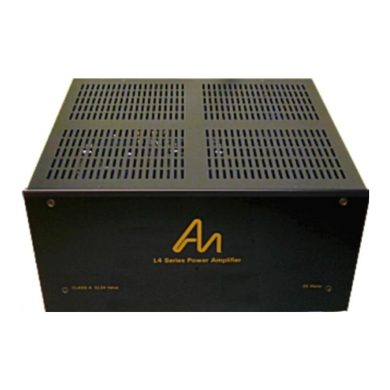
Overview Welcome to the L4 EL34p Amplifier Manual – the manual will guide you through the complete build and test of the amplifier. Please remember, if you have any questions, please don't hesitate to contact audionotekits@rogers.com. Above you can see the general layout of the amplifier: this includes, starting from top right and moving clockwise, the Mains transformer T-190 ... -
Page 9: Basic Operation Of The Amplifier
Basic Operation of the Amplifier The Audio Signal enters the amplifier via the RCA jacks on the back of the unit - the left and right audio go directly to the input of the large ECF80/EL34 PCB. This PCB connects to the Output Transformers Primary –... -
Page 10: Equipment
Equipment Here is the list of equipment that will be required: Philips screwdriver A pair of quality wire strippers A large, organized work area Soldering iron station with wet sponge Lead-based solder (4% Silver is recommended) 1.5.1 Overview of the Kit In your kit you will find a series of kit bags containing all the hardware, wire, and parts for the... -
Page 11: Resistor Sizes
1.6.3 Resistor Sizes Resistors today, particularly metal film resistors, are often smaller than you might expect. It used to be that the difference between a 1/2W and a 1W resistor was obvious: the 1W was considerably larger. That way of looking at things sometimes now no longer applies. Please be assured that all resistors supplied with ANK Audio Kits are rated at least per the specified wattage: in some cases, a higher than specified wattage may be supplied. -
Page 12: Wire Stripping And Tinning
use all stainless steel metric hardware in the kits. It truly is a thing of beauty: don’t rush your hardware! Here are a few helpful things to understand: We use British metric hardware (M3, M4, M5, screw size 10mm, 15mm, etc..) as opposed to the American imperial system (5/1000th or 50/1000th, 1 inch, 3/4 inch). -
Page 13: Optional Finishing Touches
From time to time we get asked about some of the build details of the ANK Finished Products that you can see in the pictures in the "Assembled Kits Gallery!" (https://ankits.smugmug.com/) on our website. It's important to understand that these stunningly beautiful products were done by an accomplished professional builder with decades of experience and that some particulars of the build may be beyond most of us. -
Page 14: Organization Of This Manual
1.7.2 Organization of this Manual We have divided the build up into the following sections: Section 1 Introduction Section 2 Feet, IEC and Rocker Switch Installation Section 3 Mains Transformer installation Section 4 IEC PCB Installation Section 5 Choke installation Section 6 Power Supply PCB Installation Section 7... - Page 15 Here's another way of looking at how the manual is organized and how the sections fit into the 'big picture': the main sections are mapped so that they mirror how the components will be positioned in the amplifier chassis: Copyright © 2019 AudioNote Kits www.AudioNoteKits.com audionotekits@rogers.com Page 15...
-
Page 16: Electrical Safety Warning
1.7.3 Electrical Safety Warning Please be aware of proper electrical safety. There are sufficient voltages in this kit to give you a very nasty and harmful shock, so be careful when powering on, debugging, and probing around. Please contact ANK Audio Kits via phone or email (audionotekits@rogers.com) to discuss any precautions necessary when building the kit if you feel unsure about what you are doing at any stage of the build. -
Page 17: Section 2 - Feet, Iec And Rocker Switch Installation
Section 2 Feet, IEC and Rocker Switch Installation Overview In this and the following three sections we will install the feet, IEC socket and PCB, rocker switch, Mains Transformer, and the Choke, as well as make the important initial connections to the Mains transformer. -
Page 18: Feet Installation
Feet Installation Our first task is to install the 4 rubber feet into the holes in the 4 corners of the chassis – using the provided hardware in the “Feet” bag in the big Hardware bag. Use an M4 screw along with the big washer on the outside of the foot and then a M4 nut and M4 black serrated washer against the chassis on the inside of the chassis! Might be handy to use an M4 nut driver or something similar to tighten the nuts for the feet on... -
Page 19: Iec And Rocker Switch Installation
IEC and Rocker Switch Installation Let's install the input AC receptacle (IEC plug) and rocker switch in the rear of the chassis. Here you can see the correct installation of the IEC plug in the rear of the chassis along with the rocker switch. -
Page 20: Section 3 - Mains Transformer Installation
Section 3 Mains Transformer Installation Mains Transformer Installation Let's position the Mains transformer now. It uses 2 rubber strips to isolate it from the chassis. Lay down the two rubber strips so that they are over the correct holes in the chassis – these holes are about 100mm apart from each –... -
Page 21: Section 4 - Iec Pcb Installation
Section 4 IEC PCB Installation IEC PCB Wiring The IEC PCB makes wiring the Mains transformer for your world voltage a little easier – it is mounted on the rear of the chassis in a horizontal position above and to the left of the IEC and rocker switch. - Page 22 Connect the four Primary wires as shown. The wiring is the same for both 120V and 240V systems. Copyright © 2019 AudioNote Kits www.AudioNoteKits.com audionotekits@rogers.com Page 22...
- Page 23 120V Operation ONLY Add the two jumpers as shown. Be sure to allow Complete the wiring for the rocker switch, IEC and grounds as shown. sufficient length for all wires – it's a good idea to 'lay it all out' first before cutting the wires to the appropriate length.
- Page 24 240V Operation ONLY Add one jumper as shown. Be sure to allow Complete the wiring for the rocker switch, IEC and grounds as shown. sufficient length for all wires – it's a good idea to 'lay it all out' first before cutting the wires to the appropriate length.
-
Page 25: Mounting The Iec Pcb
Once the ground lugs have been secured and the crimped connections have been made to the rocker switch and the IEC, secure the Mains transformer to the chassis using the supplied hardware. Mounting the IEC PCB Peel off the paper covering on the plastic insulating board, then, using the IEC hardware, mount the IEC PCB to the back of the amplifier as shown in the picture below: use 2 standoffs, then the PCB, 2 more standoffs, and finally the plastic insulating board. - Page 26 Time for a break! Copyright © 2019 AudioNote Kits www.AudioNoteKits.com audionotekits@rogers.com Page 26...
-
Page 27: Section 5 - Choke Installation
Section 5 Choke Installation Choke Installation Install the large Choke – called the CH-100W (which you will see marked on the underside of the unit). Note that the 2 black wires exit the Choke nearest the side panel of the chassis. Here's a picture: Copyright ©... -
Page 28: Section 6 - Power Supply Pcb Installation
Section 6 Power Supply PCB Installation Overview In this section we'll be building the Power Supply board, which is situated next to the Choke. Copyright © 2019 AudioNote Kits www.AudioNoteKits.com audionotekits@rogers.com Page 28... -
Page 29: Parts List
Parts List The Power Supply PCB will be populated with the parts from the Power Supply bag. Quantity Description Designation 1000V 3A Fast Diode D1 D2 D3 D4 .01uf 630V C18 C19 30uf 600V Square Mundorf 220uf 450V 2A – 3.15A Slow Blow FUSE FS 1A fuse clips FS 1A... -
Page 30: Mounting The Power Supply Pcb
Have a look the following picture, and Populate the board. Mounting the Power Supply PCB Install the four standoffs onto the board from the hardware bags, position it as shown in the Choke Installation section above, and secure to the bottom of the chassis with M4 10mm screws. -
Page 31: Section 7 - Ecf80/El34 Pcb Installation
Section 7 ECF80/EL34 PCB Installation Overview This is the large PCB that we will start to populate and verify. Quite a bit of work but we can take it one step at a time. We will divide up the board into several sections and take our time! The ECF80/EL34 PCB will be populated with the parts from the ECF80/EL34 bag. -
Page 32: Building The Ecf80/El34 Pcb
Building the ECF80/EL34 PCB Before we begin, let's talk for a moment about installing valve bases. The key is to Use some masking tape to secure the valve base to the board prior to soldering. make sure the valve base is level : if you have a base that is soldered in on an angle then your tube will also lean over! Generally, you'll want to solder from the underside of the board. -
Page 33: Resistor Installation
We have two 9 pin valve bases and four 8 pin CMC black valve bases. The 9 pin valve bases only go in one way BUT the 8 pin valve bases have a key or slot on them that you must match up to the PCB for correct installation. -
Page 34: Capacitor Installation
tool that does this neatly: try Googling "resistor bender".) If the leads (at right angles) are a little too wide for the holes, try to bring each 'in' a bit with a neat additional bend. When you are done you may want to compare it with our high resolution photo of a populated board on your disk. -
Page 35: Final Assembly Of The Ecf80/El34 Pcb
Film capacitors Quantity Designation Description C4-1,C4-2,C5-1,C5-2 .22uf 630V These film caps can also go into the board without an orientation. Some people feel that paying special attention to a film capacitor's 'outside foil' can make a difference – feel free to learn more: Google "film capacitor, outside foil". -
Page 36: Speaker Posts, Rca Jacks Installation
Section 8 Speaker Posts, RCA Jacks Installation Speaker Posts and RCA Jacks Installation At the rear of the chassis let's install the speaker posts and RCA jacks: The two RCA jacks install into one of the three pairs of vertically aligned holes. (We'll ... -
Page 37: Wiring The Rca Jacks
Wiring the RCA Jacks Before you wire up RCA jacks, let's discuss how to do it: When working with the RCAs jacks, we recommend the following procedure: Tin the RCA ground lead and put a puddle of solder in the center of the RCA ... -
Page 38: Section 9 - Output Transformers Installation
Section 9 Output Transformers Installation Output Transformers Installation The IE core transformers install with the Red, Black, and Yellow wires facing the ECF80/EL34 PCB. The build below positions is for the integrated amp, but the transformer positioning is the same. (The unusual orientation of the transformers is not an issue; you can position them either way.) Copyright ©... - Page 39 Examine the C core transformers closely. On one side you will see Red, Black, and Yellow dots and lugs. On the other you will see Green (larger), Blue (smaller, in the middle), and Purple (larger). Orient the transformers so that the Red, Yellow, and Black lugs face the center of the chassis.
-
Page 40: Wiring The Speaker Posts
9.1.1 Wiring the Speaker Posts Here's a diagram of what we're going to do next: Note: The following wiring instructions use only Red and Black wires as your kit may be supplied with only Red and Black wires, in lieu of the Red, Black, Blue, Green, and Purple shown in the diagram above. -
Page 41: Initial Wiring Of The Output Transformers
Now prepare the following Red wires: 4 Red wires of approximately 7". These MUST be long enough to reach from the middle and upper Red speaker posts to the Blue and Purple lugs on the Output Transformers. 2 Red wires of approximately 9". These MUST be long enough to reach from the upper Red speaker posts to the solder pads marked '8R' on the ECF80/EL34 PCB. - Page 42 Definitely time for another cup before we do the Interwiring! Copyright © 2019 AudioNote Kits www.AudioNoteKits.com audionotekits@rogers.com Page 42...
-
Page 43: Section 10 - Interwiring
Section 10 Interwiring At this stage of the kit we should have completed the major tasks of the kit build and we can now look at hooking everything up together – this is considered the INTERWIRING STAGE. This guide explains the interwiring – best to look at the higher resolution version of these slides on disk to show the details! The slide below shows the interwiring connections between the two boards. -
Page 44: Power Supply Pcb Interwiring
10.1 Power Supply PCB Interwiring Note: In the following steps, make sure to measure the wire length before cutting and tinning. Looking at the slide on the previous page: Connect the Blue and Yellow wires from the Mains Secondary to the Power Supply PCB as shown–... -
Page 45: Mains Secondary Interwiring
10.3 Mains Secondary Interwiring Looking at the slide at the beginning of this section: The orientation of the Mains Secondary wires does not matter. Either wire in a twisted pair can go to either of the designated pair of lugs. Connect the remaining wires coming from the Mains Secondary as follows: From Orange &... -
Page 46: Input Signal Interwiring
10.6 Input Signal Interwiring 10.6.1 Left/Right Channel Orientation Turn the ECF80/EL34 PCB back over again. You can choose which RCA input and which side of the ECF80/EL34 PCB are to be the Left Channel and the Right Channel. This manual and the associated slides/pictures make these designations as follows: Looking from the front of the amplifier towards the back: Left Channel –... -
Page 47: Led Installation
10.7 LED Installation Looking at the slide at the beginning of this section: The LED holder is attached to the front panel with a little adhesive and the LED is wired to the ECF80/EL34 PCB LED/PL, either way. Now, use the Interwiring Chart on the next page to carefully verify all your connections! If you are in any doubt as to any of the connections, please contact audionotekits@rogers.com Copyright ©... -
Page 48: Interwiring Chart
10.8 Interwiring Chart -------------------------------------------- ------------------------------------------- From -------------------------------------------- ------------------------------------------- Mains Transformer T-190 Twisted Yellow and Blue PS PCB AC/HT Orange & Orange/White ECF80/EL34 PCB 6V3 3A/LOOP OUT Purple CT/6V3 Red & Blue/White ECF80/EL34 PCB 6V3 6A Brown & Black/Green ECF80/EL34 PCB 6V3 6A -------------------------------------------- ------------------------------------------- Choke 100W... -
Page 49: Section 11 - Testing
Section 11 Testing OK! Your amplifier is built – take a deep breath and well done! The first thing to do is to check – and check – and check again your work! No need to insert any tubes at this point! Let's go through a series of ohm checks to make sure the amp is more or less constructed correctly! Go through the Interwiring chart and visually inspect everything. -
Page 50: Power On And Voltage Checks
11.1 Power On and Voltage Checks There are a couple of voltage basics that can really help the cause. There are two types of voltage: DC and AC. DC is a constant voltage, for example the High Voltage in a 300B amplifier is typically 425V DC, so when you measure from the high voltage point to any ground in the circuit (even the chassis), you will measure 425V DC. -
Page 51: Dc Voltage Checks
11.1.3 DC Voltage Checks Now some DC voltage checks: On the Power Supply PCB: you should have 375V DC between PS B+ and GND. Also measure the B+ and GND on the ECF80/EL34 PCB – it should be the same voltage as they are directly connected. -
Page 52: Checking Amplification
11.2.1 Checking Amplification If all your AC and DC conditions are correct then let's do an AC amplification test as a final check. Install the DUMMY 8 ohm 10W resistors across the 8 ohm speaker posts – then power on the amp and play an audio CD test through the amp. -
Page 53: Section 12 - Finishing Touches
Section 12 Finishing Touches 12.1 Installing the Front Faceplate Remove the protective films from the front and back of the front faceplate. Install the front faceplate using four Black M4 CSK flat head screws. 12.3 Installing the Chassis Top Install the chassis top using the provided hardware. Copyright ©... -
Page 54: Section 13 - Congratulations And Final Thoughts
Section 13 Congratulations and Final Thoughts 13.1 Congratulations and Final Thoughts If you make it to this point then CONGRATULATIONS! – you are ready to insert your amp into your main system and enjoy your new amplifier. 13.1.1 Tube Rolling The sound of the EL34p Power Amplifier is both classic and modern. -
Page 55: Appendix
Appendix The appendix contains auxiliary information. That is information that is either common to most project manuals or any last minute pieces of information that did not make it into the manual in time. It may also contain pull-out circuit diagrams that may be handy to have outside the manual etc. Copyright ©... -
Page 56: Resistor Color Code Reference
Resistor Color Code Reference You can also find an 'Interactive Resistor Color Code Calculator' on our website (available from the Links page). Copyright © 2019 AudioNote Kits www.AudioNoteKits.com audionotekits@rogers.com Page 56...
Need help?
Do you have a question about the L4 Series and is the answer not in the manual?
Questions and answers