
Summary of Contents for Conteg PDU
- Page 1 User manual CONTEG PDU Page 1 of 44 CONTEG PDU User Manual – firmware version 2.42...
- Page 2 How to find unit address, tag, name or location of the PRODUCT SPECIFICATIONS PDU? SERVICE AND SUPPORT How to check the way the PDU is connected to the LAN? Page 2 of 44 CONTEG PDU User Manual – firmware version 2.42...
- Page 3 Also new are the “How to..” sections. You can see this as quick problem solving parts, but only use them after ● reading the “Safety warnings” and “Expert personnel” sections in part I of this manual Described how to configure SNMPv3 ● Page 3 of 44 CONTEG PDU User Manual – firmware version 2.42...
-
Page 4: Table Of Contents
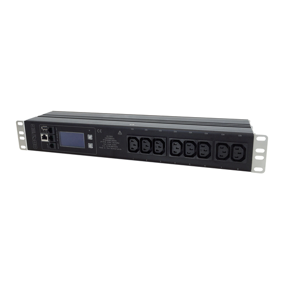
How to check the way the PDU is connected to the LAN? How to mount a PDU vertically (= 0U)? How can I check in which mode and with what protocol the PDU is How to install on a flat surface?...table top mount running? How to prevent hot spots in a cabinet? …sunken installation... - Page 5 The CONTEG Intelligent Power Distribution Unit (PDU) is designed to distribute the power. And CONTEG data bus makes it possible to read and manage many PDUs with a single IP address! This PDU adds an Ethernet port to this functionality, so that alongside the advantages of a data bus, a whole range of new options has become available.
- Page 6 OLORED HOUSING Standard the housing color of the CONTEG PDUs is black. It is also possible to anodizing the housing in 5 other colors. 01. black 02. green 03. orange 04. blue 05. red 06. yellow EASUREMENTS Measurements of the input and the outlet level can be found below:...
-
Page 7: Part I - Installation
I - I NSTALLATION Please use the information in this chapter to inspect, install and connect the CONTEG Intelligent PDU and all optional mentioned accessories. The PDU must be installed in a restricted access location Socket-outlet must be installed near the equipment... - Page 8 ESTING Each CONTEG PDU is tested according to the NEN 3140 standard. Test reports of individual PDUs are available on request. For measurement of insulation resistance, the measuring voltage used must be lower than or equal to the voltage according to the product specification.
-
Page 9: How To Mount A Pdu Horizontally (19 Inch)
How to mount a PDU horizontally (19 inch)? Each 19’’ rack bracket of a PDU has 4 holes for horizontal mounting in 19” racks. The holes are positioned so that an appropriate fixing hole is always available for a PDU with a profile height of 1.5 U. -
Page 10: How To Mount A Pdu Vertically (= 0U)
Toolless Mounts ‘Toolless Mounts’ are attachment points on the rear of the profile that allow the PDU to be hung in the cabinet without using tools. Toolless Mounting can be done as single PDU or double PDUs. In case of 2 parallel PDUs the overlapping brackets must be joined together using self-cutting screws in smaller holes on the standard bracket. -
Page 11: How To Connect The Pdu To Lan
LED – marked “lnk” - will blink How to connect a data bus? The serial data bus in the CONTEG PDU uses CAT5 or (preferable) patch cables. Each PDU features two RJ45 connectors, with which you can make a closed loop. -
Page 12: How To Connect A No/Nc Contact
How to connect a NO/NC contact? The sensor port makes use of the RJ12 6P6C standard (= 6 position, 6 conductor). To connect a NO/NC contact on the PDU sensor port, you have to make use of pin 1 and pin 6 ; as shown in the figure below. -
Page 13: Part Ii - User Manual
⇒ Before turning on the PDU for the first time, make sure that it has been allowed to acclimatize to the ambient temperature for at least 24 hours. Major temperature fluctuations can lead to the formation of condensation in the PDU if this guideline is not followed. -
Page 14: Part Iia - Locally Operating The Pdu
IIA - L OCALLY OPERATING THE The intelligent PDU features a display with scroll buttons, LEDs and some ports for connecting accessories. Please keep in mind that PDUs may differ in configuration and may not have a display. 10/100 Ethernet... -
Page 15: How To Stop A Blinking Display
Why do alerts occur? Alerts are signal flags after an event occurred. For example, if you measure temperature and the environmental conditions exceeded a configured level - threshold - the PDU will generate an alert. This resolves in: SNMP trap the screen of the PDU will start blinking. -
Page 16: How To Check An Outlet Status Locally
How to check an outlet status locally? In the “outlets” display you can see how many outlets the PDU has and what their individual state is. An overview of the possible states: scheduled to go off Note: every row on the display shows the scheduled to go on state of 9 outlets. -
Page 17: How To Read Measurements Of Optional Sensors And What Options Are Possible
It makes sense to have one or more RC-sensors inside each PDU. The search of an RC-fault can thus be limited to a single PDU or segment of that PDU. -
Page 18: How To Find Unit Address, Tag, Name Or Location Of The Pdu
= MAC address of the device ● How can I check in which mode and with what protocol the PDU is running? In the “IP Interfaces” display you can find information about the device mode in which the PDU is working: ●... -
Page 19: How To Check The Installed Firmware Version
In the “About” display you can find information regarding serial number, product information and CONTEG order number. = unique hardware address of this device’s controller ● = serial number (also found on the PDU housing) ● = product identification (also found on the PDU housing) ●... -
Page 20: Part Iib - Remote Operating And Monitoring: Web Interface
Using the web interface means using capacity of the data bus and slowing down the performance of other interfaces. Therefore it is NOT advisable to open too many web interfaces in order to prevent “hammering” the data bus. Page 20 of 44 CONTEG PDU User Manual – firmware version 2.42... -
Page 21: How To Select English Or German Language
To open protected cells, you first have to click the “Locked” sign and the status will change to “Editable”. When ready, click “Editable” or click the “Save changes” icon if shown, and the sign will turn into “Locked”. Page 21 of 44 CONTEG PDU User Manual – firmware version 2.42... - Page 22 – ASHBOARD Shown is an example of a 3 phase PDU: therefore, you see 3 loads in the “Load” section. This section gives you a quick view of the System status actual status of the PDU: are there any alerts? And if yes, what kind of alerts? NOTE: When enabled “Auto reset alert”, alerts will be...
- Page 23 See also chapter: System tab > Settings In a graphical bar the load is presented. As long as the load is under the “alert threshold” the bar will be green Page 23 of 44 CONTEG PDU User Manual – firmware version 2.42...
- Page 24 See also chapter: System tab > Settings type Shows the type of sensor. This is auto detect ➢ See also chapter: Operating the PDU > description of display screens > Sensor page(s) value Shows the actual sensor value Page 24 of 44...
- Page 25 – NPUTS This indicates the number of input phases. In this example, you see 3 lines because a 3 phase PDU is shown. A single phase PDU will show only 1 line name Default, the name has 8 characters. With the “extended name”-option enabled, you can make use of 18 characters.
- Page 26 Total amount of energy per line since the last reset. Resetting after “unlocking” and clicking the “reset” button power [VA] Apparent power per outlet Note: not available on Classic PDU (= without Ethernet port) or DPM27 power [W] Real power per outlet Note: not available on Classic PDU (= without Ethernet port) or DPM27...
- Page 27 After you have made a choice, the state of the outlet is changing ( See “state” in this table) While the given command is running, a status bar shows the progression of the action. Page 27 of 44 CONTEG PDU User Manual – firmware version 2.42...
- Page 28 – YSTEM On the next pages the different sections of this tab are described. Page 28 of 44 CONTEG PDU User Manual – firmware version 2.42...
- Page 29 Note: this field is not connected with the “extended name support” and always max 16 characters vanity tag Configurable vanity tag, which has maximal 20 characters Note: this field is not connected with the “extended name support” and always max 20 characters Page 29 of 44 CONTEG PDU User Manual – firmware version 2.42...
- Page 30 (manually / automatically) restart CPU This is a reboot of the controller of the PDU. After restarting all alerts and peak registrations will be erased. Be assured: power distribution will NOT BE INTERRUPTED during this restart! reset alerts Clears all the alerts on the device.
- Page 31 Configurable time in milliseconds that a current overload can occur before an alert is given. [msec] Note: do not make this time too short because otherwise alerts keep on raising! Page 31 of 44 CONTEG PDU User Manual – firmware version 2.42...
- Page 32 [msec] and values below 100 milliseconds are not accepted. outlet power up Shows the behavior of the outlets when a PDU is powered. mode It can be set as: off: at power up, all the outlets are kept in the off state.
- Page 33 – NTERFACES The sections of this screen are described in specific manuals. These can be downloaded from our website: http://download.conteg.com/PDU/IP-S/ Page 33 of 44 CONTEG PDU User Manual – firmware version 2.42...
-
Page 34: Part Iii - Administrator Manual
To change the settings of a specific user click the ‘edit’ button. Then check the ‘change snmpv3 settings’ checkbox to edit the snmpv3 settings. When finished, click the ‘save user’ button. Page 34 of 44 CONTEG PDU User Manual – firmware version 2.42... -
Page 35: How To Use The 'Connected Devices' Section In The Web Interface
(or below the blue header when using narrower displays). Initially this list is empty but will be filled while the web interface is loading data from the bridge-PDU. A selected device is marked - yellow line - in the device list (left pane). You can switch to another device just by clicking the row in the device list. -
Page 36: How To Change Factory Passwords
If this setting is changed in the wrong way and you are not able to connect, change the setting of the link partner to be able to access the PDU again. If this doesn’t work you can try a factory reset. -
Page 37: How To Configure The Ip Settings Manually
Domain Name System (DNS) servers ● By default, the PDU is configured to get the IP address from DHCP automatically. If the PDU does not receive an IP address within a set time, it will proceed using the default address: 192.168.1.220... -
Page 38: How To Upgrade The Firmware
From firmware 2.40 on it will be possible to select a duration time after which the alert will be cleared after the cause of the alert is not present anymore. It will be no longer necessary to clear the alert on the PDU or via an interface after the event which led to an alert is gone But remember: an alert does not occur without a reason. - Page 39 The intelligence of CONTEG PDUs (and DPM energy Advantages of the data bus: meters) makes it possible to read and manage devices easy to build: just pick a PDU and connect it to ● remotely over IP. You can for example enter the data bus your LAN, daisy chain the rest of the PDUs and via the web interface, MODBUS and SNMP.
-
Page 40: How To Prevent Data Losses Because Of Cable Cuts
How to prevent data losses because of cable cuts? ...ring redundancy Normally the advantage of an IP solution per PDU is that a cable cut will not affect the other PDUs on the bus. This could happen in a normal daisy chained serial bus topology. -
Page 41: How To Make A Data Bus Using Gateway
PDUs connected to the Gateway. Advantage: with one IP-address you can collect data The Classic PDU has NO ethernet port, so a (CONTEG) from a number of connected CONTEG-devices (not only Gateway is needed in order to get PDUs connected to PDUs but also the DPM-range (=energy meters) your LAN. -
Page 42: How To Connect The Data Bus To Lan Without A Gateway
How to connect the data bus to LAN without a Gateway? ...using a PDU In the figure you see a small data bus-ring with only four device which is in BRIDGE-mode. In a closed data bus devices connected to a LAN: a Classic PDU and PDU with ring you can reach all connected devices via IN and OUT ethernet port. -
Page 43: Maintenance & Troubleshooting
Software reset can be done via the web interface. It is important to understand that a software reset has no impact on power distribution of the PDU. So a reset can be performed at any time without having to interrupt the power supply and without losing the settings in the PDU. - Page 44 © CONTEG is a registered trademark. This publication is protected by copyright. No part of it may be reproduced or transmitted in any form, without prior consent in writing from CONTEG. Page 44 of 44 CONTEG PDU User Manual – firmware version 2.42...
Need help?
Do you have a question about the PDU and is the answer not in the manual?
Questions and answers