Advertisement
ALIMENTATION SMART 4 in 1 - 24 VDC
AVERTISSEMENT : L'installation doit être réalisée par des personnes qualifiées en respectant les normes et réglementations en vigueur. Il est rappelé que la décision d'installation des produits dans un environnement compatible et conforme aux normes et règles de l'art, est de la responsabilité pleine
FR
et entière de l'acheteur et de l'installateur. Lisez et respectez les instructions avant d'installer, de mettre sous tension ou d'utiliser les produits. Nous déclinons toute responsabilité résultant d'une mise en œuvre ou d'une installation inappropriée des produits.
Les appareils ne doivent pas être modifiés, même partiellement, faute de quoi la garantie ne pourra s'appliquer.
IMPORTANT : Toujours couper le courant au niveau du réseau avant chaque opération d'installation ou de maintenance.
Alimentation AC /
AC power /
Entrée signal Triac
Tria c signal input
L
N
SEC :
FG
Outpu t Voltage=24VDC
90
I
INPU T:
rated=8.3A max
45
DA
220-240V~ 1A 50/60Hz
Prated=200 W ma x
>0.95@230V AC
DA
PUS H DI M
L
DA
N
DA
NC=None connec t
Suitable for Dam p Location s (CONVIEN T AU X EMPLACEMENTS HUMIDES )
Ecran digital
Entrée Commande
Digita l display
DALI/AC pus h intput
DALI/AC
1. SPÉCIFICATIONS TECHNIQUES
Sortie commande LED
1 (avec 2 groupes de sortie en parallèle)
Tension constante
Max 4,16A/groupe de sortie (groupe1+groupe2 =
Sortie
Courant Max
Tolerance de tension
Puissance
Plage de tension
Plage de fréquence
Facteur de puissance
Distorsion harmonique totale
2. Set DALI Address Manually While Connected with DALI Input
Entrée
Rendement
2.1 Press and hold down any of the two buttons until numeric digital display flashes, then release
the button.
2.2 Click any of the two buttons once to select a digit, click again to change the digit until the
Courant AC
desired DALI address appears. Click first button to set "tens" position and second button to set
"units" position. The address can be set from 00~63.
Pic de courant
2.3 Then press and hold down any of the 2 buttons until the numeric digital display stops flashing
0-6
0-9
to confirm the setting.
Courant de fuite
Note: DALI address can be manually assigned from 00-63-FF, by factory defaults, no DALI
Interface de variation
address is assigned for the driver, and the display shows
Variation
will reset the dimmer to factory defaults.
Plage de variation
3. DALI Address Assigned by DALI Masters
Méthode de variation
Modulation de largeur d'impulsion
3.1 DALI address can also be assigned by DALI Master controller automatically, please refer to user manuals of
compatible DALI Masters for specific operations.
Oui, rétablissement automatique après la fin du
Court circuit
Note: The digital display will show
when the DALI master is assigning addresses.
4.PUSH Dimmer Mode
Oui, rétablissement automatique après la fin du
Protection
Surintensité
While connected with a AC push switch, the digital display will show "PD" which means Push Dimmer
Mode, operations under PUSH Mode are as follows:
4.1. Click the button to switch ON/OFF
Oui, rétablissement automatique après la fin du
Surchauffe
4.2. Press and hold down the button to increase or decrease light intensity to desired level and release it, then
repeat the operation to adjust light intensity to opposite direction. The dimming range is from 1% to 100%.
4.3. Memory function after power off or power failure enables the device to memorize the status before power
off while power on again.
5. Triac Dimming Input
While connected with a Triac dimmer, different Triac dimmers from different suppliers may have different
minimum dimming levels which the driver can not be dimmed below. To dim to 1%, please make sure the
dimmer supports 1% minimum dimming level.
Wiring diagram
1.With DALI bus
Environ-
nement
Sortie commande LED
1 chane l LED outpu t
NC
NC
Sortie signal 0/1-10V
GN D
0/1-10V signa l input
0- 60
-9
NC
NC
NC
Sécurité et
CEM
2. Set DALI Address Manually While Connected with DALI Input
Autre
0-6
24V DC
1.
4 possibilités de variation : DALI, Bouton poussoir, Triac, 0/1-10V
8,32A)
2.
N'utiliser qu'une seule solution de variation à la fois
3.
L'écran affichera automatiquement un code correspondant à la solution de variation câblée
± 1%
sur le produit :
3. DALI Address Assigned by DALI Masters
3.1 DALI address can also be assigned by DALI Master controller automatically, please refer to user manuals of
max 200W
compatible DALI Masters for specific operations.
TRIAC
220-240V AC
Note: The digital display will show
4.PUSH Dimmer Mode
50/60Hz
While connected with a AC push switch, the digital display will show "PD" which means Push Dimmer
2. SCHÉMA DE CÂBLAGE
Mode, operations under PUSH Mode are as follows:
>0,95@230VAC
4.1. Click the button to switch ON/OFF
4.2. Press and hold down the button to increase or decrease light intensity to desired level and release it, then
repeat the operation to adjust light intensity to opposite direction. The dimming range is from 1% to 100%.
THD⩽15% (@chargé / 230VAC)
TRIAC
4.3. Memory function after power off or power failure enables the device to memorize the status before power
3.With Triac Dimmer
off while power on again.
93% @ 230VAC chargé
5. Triac Dimming Input
While connected with a Triac dimmer, different Triac dimmers from different suppliers may have different
L N GND
minimum dimming levels which the driver can not be dimmed below. To dim to 1%, please make sure the
1A @ 230VAC
dimmer supports 1% minimum dimming level.
Wiring diagram
65A @230VAC
1.With DALI bus
L N GND
< 0,5mA/230VAC
DALI/Bouton+Triac+0/1-10V
. Setting DALI address as
0,1%-100%
L N GND
défaut
2.With PUSH dimmer
L N GND
défaut
défaut
4.With 0/1-10V dimmer
L N GND
NOTICE D'UTILISATION MULTILINGUE EUROPOLE - n°246 - V1 - 02/05/2019 - ALIMENTATION SMART 4 in 1 - 24 VDC
EUROPOLE - 19, avenue ZAC de Chassagne - 69360 TERNAY - Fax : +33 (0)4 72 24 73 42 - www.europole.net
Température de fonctionnement
-25°C ~ +45°C
Température max du boitier
90°C
Humidité de fonctionnement
10%~ 95% Humidité relative
Température de stockage et
-40°C ~ +80°C, 10%~ 95% HR
humidité
Standard de sécurité
EN61347-1,EN61347-3-13 approuvé
Tension de tenu
I/P-O/P:3,75KVAC
Résistance d'isolement
I/P-O/P:100M Ohms / 500VDC / 25°C / 70% HR
Emission CEM
EN61347-1, EN61000-3-2,EN6111-3-3
EN61547,EN61000-4-2,3,4,5,6,8,11, immunité
2.1 Press and hold down any of the two buttons until numeric digital display flashes, then release
Immunité CEM
surtention ligne-ligne 1kV
the button.
2.2 Click any of the two buttons once to select a digit, click again to change the digit until the
Temps moyen entre panne
desired DALI address appears. Click first button to set "tens" position and second button to set
193,6k Heures minimum @230VAC chargé et 25°C
"units" position. The address can be set from 00~63.
2.3 Then press and hold down any of the 2 buttons until the numeric digital display stops flashing
Dimensions
240*72*36mm(L*l*H)
0-9
to confirm the setting.
Note: DALI address can be manually assigned from 00-63-FF, by factory defaults, no DALI
address is assigned for the driver, and the display shows
will reset the dimmer to factory defaults.
Bouton poussoir
DALI
(Push dim)
when the DALI master is assigning addresses.
Triac dimmer (No Neutral Wire)
Variateur Triac (sans fil neutre)
V+
V-
(AWG18-10)
(AWG20-14)
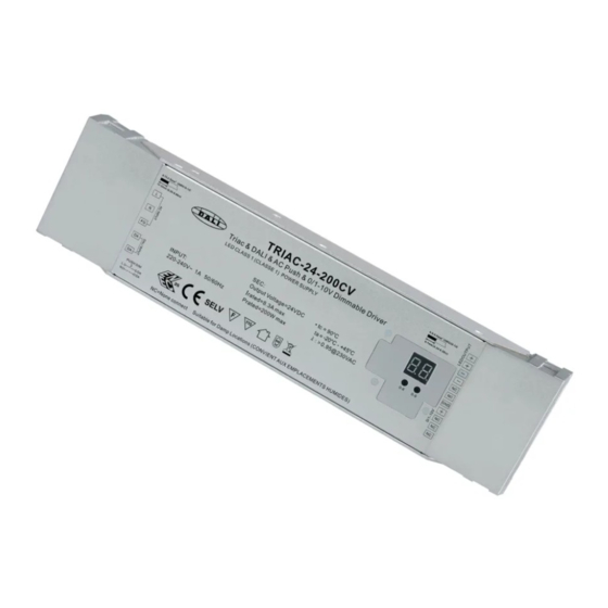
Triac & DALI & AC Push & 0/1-10V Dimmable Driver
(0.55-0.86in)
(0.24-0.28in)
L
LED CLASS 1 (CLASSE 1) POWER SUPPLY
N
NC
SEC:
FG
Output Voltage=24VDC
NC
90
INPUT:
I
rated=8.3A max
ta
45
GND
220-240V~ 1A 50/60Hz
DA
Pout=200W max
λ >0.95@230VAC
:
0-6
0-9
NC
DA
NC
V+
PUSH DIM
NC
L
DA
NC=None connect
(AWG18-10)
Suitable for Damp Locations (CONVIENT AUX EMPLACEMENTS HUMIDES)
V-
N
DA
(AWG20-14)
(0.55-0.86in)
Triac & DALI & AC Push & 0/1-10V Dimmable Driver
(0.24-0.28in)
L
LED CLASS 1 (CLASSE 1) POWER SUPPLY
N
NC
SEC:
FG
NC
Output Voltage=24VDC
90
INPUT:
I
rated=8.3A max
ta
45
GND
220-240V~ 1A 50/60Hz
DA
Pout=200W max
λ >0.95@230VAC
:
0-6
0-9
NC
DA
NC
PUSH DIM
NC
L
DA
NC=None connect
Suitable for Damp Locations (CONVIENT AUX EMPLACEMENTS HUMIDES)
N
DA
Triac dimmer (With Neutral Wire)
Variateur Triac (avec fil neutre)
DALI bus
V+
(AWG18-10)
V-
(AWG20-14)
(0.55-0.86in)
Triac & DALI & AC Push & 0/1-10V Dimmable Driver
(0.24-0.28in)
L
LED CLASS 1 (CLASSE 1) POWER SUPPLY
N
NC
SEC:
FG
NC
Output Voltage=24VDC
90
INPUT:
I
rated=8.3A max
ta
45
GND
V+
DA
220-240V~ 1A 50/60Hz
Pout=200W max
λ >0.95@230VAC
:
0-6
0-9
(AWG18-10)
V-
(AWG20-14)
NC
(0.55-0.86in)
Triac & DALI & AC Push & 0/1-10V Dimmable Driver
DA
(0.24-0.28in)
L
LED CLASS 1 (CLASSE 1) POWER SUPPLY
NC
PUSH DIM
NC
L
DA
NC=None connect
Suitable for Damp Locations (CONVIENT AUX EMPLACEMENTS HUMIDES)
N
DA
N
NC
SEC:
FG
NC
Output Voltage=24VDC
90
INPUT:
I
rated=8.3A max
ta
45
GND
DA
220-240V~ 1A 50/60Hz
Pout=200W max
λ >0.95@230VAC
:
0-6
0-9
NC
DA
NC
PUSH DIM
NC
L
DA
NC=None connect
Suitable for Damp Locations (CONVIENT AUX EMPLACEMENTS HUMIDES)
N
DA
AC PUSH
V+
(AWG18-10)
V-
(AWG20-14)
Triac & DALI & AC Push & 0/1-10V Dimmable Driver
(0.55-0.86in)
(0.24-0.28in)
L
LED CLASS 1 (CLASSE 1) POWER SUPPLY
N
NC
SEC:
FG
Output Voltage=24VDC
NC
90
INPUT:
I
GND
rated=8.3A max
ta
45
220-240V~ 1A 50/60Hz
λ >0.95@230VAC
DA
Pout=200W max
:
0-6
0-9
the button.
compatible DALI Masters for specific operations.
2.2 Click any of the two buttons once to select a digit, click again to change the digit until the
desired DALI address appears. Click first button to set "tens" position and second button to set
Note: The digital display will show
"units" position. The address can be set from 00~63.
4.PUSH Dimmer Mode
2.3 Then press and hold down any of the 2 buttons until the numeric digital display stops flashing
0-6
0-9
to confirm the setting.
While connected with a AC push switch, the digital display will show "PD" which means Push Dimmer
Note: DALI address can be manually assigned from 00-63-FF, by factory defaults, no DALI
Mode, operations under PUSH Mode are as follows:
4.1. Click the button to switch ON/OFF
address is assigned for the driver, and the display shows
4.2. Press and hold down the button to increase or decrease light intensity to desired level and release it, then
repeat the operation to adjust light intensity to opposite direction. The dimming range is from 1% to 100%.
will reset the dimmer to factory defaults.
4.3. Memory function after power off or power failure enables the device to memorize the status before power
off while power on again.
3. DALI Address Assigned by DALI Masters
5. Triac Dimming Input
3.1 DALI address can also be assigned by DALI Master controller automatically, please refer to user manuals of
While connected with a Triac dimmer, different Triac dimmers from different suppliers may have different
compatible DALI Masters for specific operations.
minimum dimming levels which the driver can not be dimmed below. To dim to 1%, please make sure the
dimmer supports 1% minimum dimming level.
Note: The digital display will show
DALI
Wiring diagram
4.PUSH Dimmer Mode
1.With DALI bus
While connected with a AC push switch, the digital display will show "PD" which means Push Dimmer
L N GND
Mode, operations under PUSH Mode are as follows:
4.1. Click the button to switch ON/OFF
4.2. Press and hold down the button to increase or decrease light intensity to desired level and release it, then
repeat the operation to adjust light intensity to opposite direction. The dimming range is from 1% to 100%.
(0.55-0.86in)
4.3. Memory function after power off or power failure enables the device to memorize the status before power
L
N
off while power on again.
FG
5. Triac Dimming Input
DA
DA
While connected with a Triac dimmer, different Triac dimmers from different suppliers may have different
PUSH DIM
L
N
minimum dimming levels which the driver can not be dimmed below. To dim to 1%, please make sure the
dimmer supports 1% minimum dimming level.
DALI bus
Wiring diagram
2.With PUSH dimmer
Modifier l'adresse DALI lorsque que le produit est contrôlé par un bus DALI :
1.With DALI bus
L N GND
L N GND
- Appuyer sur l'un des 2 boutons jusqu'à ce que l'écran digital clignote
- Appuyer sur le bouton sous le chiffre à modifier, l'adresse dois être comprise entre 00 et 63
- Appuyer sur l'un des 2 boutons jusqu'à ce que l'écran digital arrête de clignoter
(AWG18-10)
(0.55-0.86in)
L
3.With Triac Dimmer
N
(0.55-0.86in)
L
Note : Par défaut le contrôleur n'a pas d'adresse assigné. Assigner
FG
N
DA
FG
paramètres d'usine.
DA
DA
PUSH DIM
L N GND
Triac dimmer (No Neutral Wire)
L
N
DA
PUSH DIM
L
N
AC PUSH
BOUTON POUSSOIR
DALI bus
2.With PUSH dimmer
L N GND
. Setting DALI address as
(AWG18-10)
(0.55-0.86in)
L
N
FG
DA
L N GND
Triac dimmer (With Neutral Wire)
DA
PUSH DIM
L
N
1-10V
AC PUSH
BOUTON POUSSOIR 0/1-10V
4.With 0/1-10V dimmer
L N GND
LED light
V+
V-
LED light
V+
V-
Product Dimension
LED light
V+
V-
LED light
V+
V-
240.00 mm
LED light
V+
V-
when the DALI master is assigning addresses.
. Setting DALI address as
when the DALI master is assigning addresses.
LED light
V+
V+
(AWG18-10)
V-
V-
(AWG20-14)
Triac & DALI & AC Push & 0/1-10V Dimmable Driver
LED CLASS 1 (CLASSE 1) POWER SUPPLY
(0.24-0.28in)
NC
SEC:
Output Voltage=24VDC
90
NC
INPUT:
rated=8.3A max
I
ta
45
GND
220-240V~ 1A 50/60Hz
Pout=200W max
λ >0.95@230VAC
:
0-6
0-9
NC
NC
DA
NC
NC=None connect
Suitable for Damp Locations (CONVIENT AUX EMPLACEMENTS HUMIDES)
DA
LED light
V+
V+
V-
V-
(AWG20-14)
Triac & DALI & AC Push & 0/1-10V Dimmable Driver
LED light
V+
V+
(0.24-0.28in)
LED CLASS 1 (CLASSE 1) POWER SUPPLY
V-
V-
(AWG18-10)
(AWG20-14)
Triac & DALI & AC Push & 0/1-10V Dimmable Driver
(0.24-0.28in)
LED CLASS 1 (CLASSE 1) POWER SUPPLY
NC
SEC:
Output Voltage=24VDC
NC
remet le contrôleur aux
90
INPUT:
rated=8.3A max
I
45
GND
ta
220-240V~ 1A 50/60Hz
Pout=200W max
λ >0.95@230VAC
NC
SEC:
:
0-6
0-9
Output Voltage=24VDC
NC
90
NC
INPUT:
I
rated=8.3A max
45
GND
ta
NC
220-240V~ 1A 50/60Hz
Pout=200W max
λ >0.95@230VAC
:
0-6
0-9
NC
DA
NC=None connect
Suitable for Damp Locations (CONVIENT AUX EMPLACEMENTS HUMIDES)
DA
NC
NC
NC
DA
NC=None connect
Suitable for Damp Locations (CONVIENT AUX EMPLACEMENTS HUMIDES)
DA
LED light
V+
V+
(AWG18-10)
V-
V-
(AWG20-14)
(0.55-0.86in)
Triac & DALI & AC Push & 0/1-10V Dimmable Driver
(0.24-0.28in)
L
LED CLASS 1 (CLASSE 1) POWER SUPPLY
N
NC
SEC:
FG
NC
Output Voltage=24VDC
90
INPUT:
rated=8.3A max
I
ta
45
GND
220-240V~ 1A 50/60Hz
DA
Pout=200W max
λ >0.95@230VAC
:
0-6
0-9
NC
DA
NC
PUSH DIM
NC
L
DA
NC=None connect
Suitable for Damp Locations (CONVIENT AUX EMPLACEMENTS HUMIDES)
N
DA
LED light
V+
V+
V-
V-
(AWG20-14)
Triac & DALI & AC Push & 0/1-10V Dimmable Driver
(0.24-0.28in)
LED CLASS 1 (CLASSE 1) POWER SUPPLY
NC
SEC:
NC
Output Voltage=24VDC
90
INPUT:
I
rated=8.3A max
ta
45
GND
220-240V~ 1A 50/60Hz
Pout=200W max
λ >0.95@230VAC
:
0-6
0-9
NC
NC
NC
DA
NC=None connect
Suitable for Damp Locations (CONVIENT AUX EMPLACEMENTS HUMIDES)
DA
LED light
V+
V+
(AWG18-10)
V-
V-
(AWG20-14)
Triac & DALI & AC Push & 0/1-10V Dimmable Driver
(0.55-0.86in)
(0.24-0.28in)
L
LED CLASS 1 (CLASSE 1) POWER SUPPLY
N
NC
SEC:
FG
Output Voltage=24VDC
90
NC
INPUT:
I
rated=8.3A max
ta
45
GND
DA
220-240V~ 1A 50/60Hz
Pout=200W max
λ >0.95@230VAC
:
0-6
0-9
NC
DA
NC
PUSH DIM
NC
L
DA
NC=None connect
Suitable for Damp Locations (CONVIENT AUX EMPLACEMENTS HUMIDES)
N
DA
LED light
V+
V+
(AWG18-10)
V-
V-
(AWG20-14)
(0.55-0.86in)
Triac & DALI & AC Push & 0/1-10V Dimmable Driver
(0.24-0.28in)
L
LED CLASS 1 (CLASSE 1) POWER SUPPLY
N
NC
SEC:
FG
NC
Output Voltage=24VDC
90
INPUT:
I
rated=8.3A max
ta
45
GND
DA
220-240V~ 1A 50/60Hz
Pout=200W max
λ >0.95@230VAC
:
0-6
0-9
NC
DA
NC
PUSH DIM
NC
L
DA
N
DA
NC=None connect
Suitable for Damp Locations (CONVIENT AUX EMPLACEMENTS HUMIDES)
0/1-10V
Variateur
Control Unit
0/1-10V
0-6
0-9
1
Advertisement
Table of Contents

Summary of Contents for EUROPOLE ALIMENTATION SMART 4 in 1
- Page 1 DALI master is assigning addresses. “units” position. The address can be set from 00~63. EUROPOLE - 19, avenue ZAC de Chassagne - 69360 TERNAY - Fax : +33 (0)4 72 24 73 42 - www.europole.net 4.PUSH Dimmer Mode 2.3 Then press and hold down any of the 2 buttons until the numeric digital display stops flashing...
- Page 2 DALI master is assigning addresses. “units” position. The address can be set from 00~63. EUROPOLE - 19, avenue ZAC de Chassagne - 69360 TERNAY - Fax : +33 (0)4 72 24 73 42 - www.europole.net 4.PUSH Dimmer Mode 2.3 Then press and hold down any of the 2 buttons until the numeric digital display stops flashing...
-
Page 3: Technische Specificaties
DALI master is assigning addresses. “units” position. The address can be set from 00~63. EUROPOLE - 19, avenue ZAC de Chassagne - 69360 TERNAY - Fax : +33 (0)4 72 24 73 42 - www.europole.net 4.PUSH Dimmer Mode 2.3 Then press and hold down any of the 2 buttons until the numeric digital display stops flashing... - Page 4 DALI master is assigning addresses. “units” position. The address can be set from 00~63. EUROPOLE - 19, avenue ZAC de Chassagne - 69360 TERNAY - Fax : +33 (0)4 72 24 73 42 - www.europole.net 4.PUSH Dimmer Mode 2.3 Then press and hold down any of the 2 buttons until the numeric digital display stops flashing...
-
Page 5: Technische Spezifikationen
DALI master is assigning addresses. “units” position. The address can be set from 00~63. EUROPOLE - 19, avenue ZAC de Chassagne - 69360 TERNAY - Fax : +33 (0)4 72 24 73 42 - www.europole.net 4.PUSH Dimmer Mode 2.3 Then press and hold down any of the 2 buttons until the numeric digital display stops flashing... -
Page 6: Specifiche Tecniche
DALI master is assigning addresses. “units” position. The address can be set from 00~63. EUROPOLE - 19, avenue ZAC de Chassagne - 69360 TERNAY - Fax : +33 (0)4 72 24 73 42 - www.europole.net 4.PUSH Dimmer Mode 2.3 Then press and hold down any of the 2 buttons until the numeric digital display stops flashing...
Need help?
Do you have a question about the ALIMENTATION SMART 4 in 1 and is the answer not in the manual?
Questions and answers