
Related Manuals for Atlas IED ASP-MG24


Summary of Contents for Atlas IED ASP-MG24
- Page 1 ASP-MG24 / ASP-MG24TDB Signal Processor / Masking Generator 2 Input x 4 Output 1601 JACK MCKAY BLVD. TELEPHONE: (800) 876-3333 AtlasIED.com ENNIS, TEXAS 75119 U.S.A. SUPPORT@ATLASIED.COM – 1 –...
-
Page 2: Table Of Contents
ASP-MG24 Owner’s Manual Table of Contents Important Safety Instructions ....................................3 Introduction ........................................... 5 Key Features .......................................... 5 Front Panel Description ......................................6 Rear Panel Description ......................................7 Getting to Know the Software....................................8 Mic / Line Input ........................................9 Masking Generator Inputs .................................... -
Page 3: Important Safety Instructions
ASP-MG24 Owner’s Manual Important Safety Instructions The lightning flash with arrowhead symbol within an equilateral triangle, is intended to alert the user to the presence of uninsulated “dangerous voltage “ within the product’s enclosure that may be of sufficient magnitude to constitute a risk of electric shock to persons. - Page 4 ASP-MG24 Owner’s Manual WARNING - When The Device Is In Use • WARNING: The terminals marked with symbol of may be of sufficient magnitude to constitute a risk of electric shock. The external wiring connected to the terminals requires installation by an instructed person or the used of ready-made leads or cords.
-
Page 5: Introduction
Control parameters include I/O levels, delay, polarity, parametric EQ, crossover selections, 31 band EQ, white / pink noise, auto ramp, routing, mixing and compressor / limiters. The ASP-MG24 can be controlled or configured in real time with the intuitive PC GUI, accessed via the RS-232 or USB interface. -
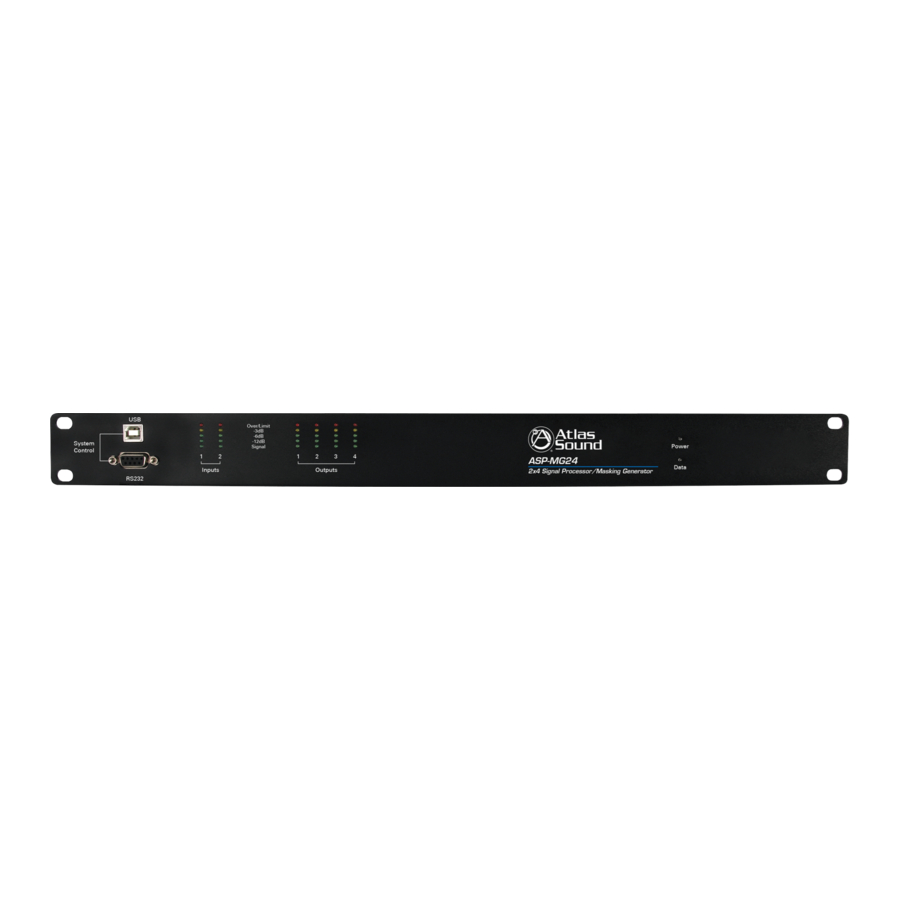
Page 6: Front Panel Description
Standard female USB socket. A straight through cable is required for PC connection. 5. LED Data Indicator The Data LED will illuminate green when there is connection made between the ASP-MG24 and the computer. 1601 JACK MCKAY BLVD. TELEPHONE: (800) 876-3333 AtlasIED.com... -
Page 7: Rear Panel Description
Rear Panel 1. Power Supply Socket An external UL rated 120V AC power supply has been included with the ASP-MG24. Only use the provided power supply due to the specific DC voltages required to operate the unit. 2. Input Connectors There are two removable 3 Pin Phoenix type connectors for providing input signal to the unit. -
Page 8: Getting To Know The Software
3. To enter the control panel screen, click on the “Device 1” button. Note: A password can be inserted at any time. Click “Start” and then “Log On” . Open the Device panel by clicking on “Device 1” . Note: An ASP-MG24 is also known as a “Device” . Multiple ASP-MG24 units can be controlled via one GUI interface. -
Page 9: Mic / Line Input
ASP-MG24 Owner’s Manual Mic / Line Input Input Meter The bar graph meter illustrates the level of the input signal POST the channel’s gain control and is PRE input filters and compressor settings. Gain For convenience both Mic / Line inputs and the four masking generators levels are shown. Controlling the gain can be accomplished by dragging the fader, using the up / down buttons or by typing in the number viewing text box. - Page 10 ASP-MG24 Owner’s Manual Compressor Inputs 1 & 2 have fully adjustable compressor limiters. When clicking on the compressor tab, two sub viewing screens will appear. Note: All control boxes can be dragged for desired positioning of the screen. Screen 1 is an indicator screen showing the compressor / limiter operation. The second is the settings screen.
- Page 11 ASP-MG24 Owner’s Manual Filter When clicking on the filter button 3 sub viewing screens appear. There are 8 bands of full parametric EQ and Hi Cut / Lo Cut filters available per input. Note: If the screens do not appear change the screen resolution. Also use the screen curser up / down arrows to find the three screens. All 3 screens can be moved by clicking and holding the selected screen for personal viewing preferences.
- Page 12 ASP-MG24 Owner’s Manual Crossover Window The Crossover window allows the adjustment of filter type, frequency, and slope. The Reset button will set all filters back to factory settings and only affects the settings on this screen. Mute This button mutes the signal at the input of the channel. It will illuminate red when pressed.
-
Page 13: Masking Generator Inputs
ASP-MG24 Owner’s Manual Masking Generator Inputs Meter There are four bar graph meters that illustrate the level of the output signal of the generator. It is POST the channel’s gain control and PRE input filters. Masking When the Masking button is pressed a small window will open. This window allows the selection of either the White or Pink noise filter. - Page 14 ASP-MG24 Owner’s Manual Gain For convenience both Mic / Line Inputs and the 4 masking generators levels are shown. Controlling the gain can be accomplished by dragging the fader, using the up / down buttons, or typing in the number viewing text box. Channel Mute can be accomplished by clicking on the Mute button. It will illuminate red indicating the channel is in Mute.
- Page 15 ASP-MG24 Owner’s Manual 1/3 Octave Graphic Screen Adjustments to the filters can be made dragging the filter number on the screen or by using the up / down arrows. The Reset button will set all filters back to factory settings and only effects the settings in this screen. There are 20 octave band filters available to adjust the measured masking signal.
-
Page 16: Masking Generator Outputs
ASP-MG24 Owner’s Manual Masking Generator Outputs Mixer This button will route or mix any of the inputs to this output. When clicking on this button a window will appear that shows all 6 inputs. Each input channel gain operates from Off to 0dB. Controlling the mixed gain can be accomplished by dragging the fader, using the up / down buttons, or typing in the number viewing text box. - Page 17 ASP-MG24 Owner’s Manual Filter When clicking on the filter screen 3 sub viewing screens appear. This allows access to 8 full parametric EQ’s per output channel. Note: All 3 screens can be moved for personal viewing preferences. Graphic Screen This screen will display all of the filter characteristics that are set.
- Page 18 ASP-MG24 Owner’s Manual Crossover Window The Crossover window allows the adjustment of filter type, frequency, and slope. The Reset button will set all filters back to factory settings. This Reset button only effects the settings in this screen. Delay Window The Delay window allows adjustment of the channel delay from 0ms to 200ms per output.
- Page 19 ASP-MG24 Owner’s Manual Limiter All 4 outputs have fully adjustable hard limiters. When clicking on the limiter tab, 2 sub viewing screens will appear. Note: All control boxes can be dragged for desired positioning of the screen. Screen 1 is an indicator screen showing the compressor / limiter operation. Screen 2 is the settings screen which controls Threshold, Attack, Release and Ratio.
- Page 20 ASP-MG24 Owner’s Manual Mute Channel Mute can be accomplished by clicking on the Mute tab and will illuminate red indicating the channel is in Mute. Output Meter The bar graph meter illustrates the level of the output signal POST the channels gain control and filters but is PRE Limiter settings.
-
Page 21: File Import And Export
ASP-MG24 Owner’s Manual File Import and Export Master Reset All This button is the master reset button and will override all settings. Note: A confirmation widow will pop up. File Open Program files can be recalled from the PC or Laptop. It operates like any other Windows files storing device. - Page 22 Device Store The ASP-MG24 has a built in non-volatile memory that can store up 14 different program setups. A program can be stored using this menu. The old program with the same program number will be replaced. Once the program is stored in the flash memory, it can be recalled at a later time, even after loss of power.
- Page 23 ASP-MG24 Owner’s Manual All Programs Upload / download up to 14 programs containing multiple loudspeaker EQ parameters and sound masking setups. Meter Real time meters for all inputs / outputs. Scaled in V(RMS), dBu and dBV. These are helpful when troubleshooting.
- Page 24 ASP-MG24 Owner’s Manual For Retrofit Sound Masking installations where the occupants are already in the space, this feature programs a one-time slow ramp to allow the occupants to become accustomed to the masking sound in the space. 1. Click the Initial Ramp Commission button.
- Page 25 ASP-MG24 Owner’s Manual The Scheduler allows the installer to program masking level changes over a 24 hour period, 7 days a week. A separate schedule can be configured for every day and can be copied to any of the 4 masking channels and the 2 inputs. This example shows Masking channel M1, with a program for Monday, ramping up slowly starting at 5am and ramping down starting at 4pm.
-
Page 26: Specifications
ASP-MG24 Owner’s Manual System Type DSP Controller 2x4 Speaker Processor / Masking Generator Power Supply Type 90 - 240VAC 20W Universal UL Rated External DC Power Supply Front Panel Level Meters In / Out 5 Segment LED RS-232 Female DB-9... - Page 27 ASP-MG24 Owner’s Manual Electrical Specifications (General) Input Impedance Line 10k Ohms, Mic Output Impedance 50 Ohms Maximum Input & Output Level +20dBu Frequency Response 20Hz - 20kHz (+/- 0.1dB) Dynamic Range 115dB (unweighted) CMMR > 60dB (50 to 10kHz) Crosstalk <...
- Page 28 ASP-MG24 Owner’s Manual Dimensional Drawings 19.00 [483] Over/Limit -3dB 1.75 -6dB -12dB System Power Signal Control [44] ASP-MG24 Data Inputs Outputs 2x4 Signal Processor/Masking Generator RS232 [203] 17.00 [431] 1.75 [44] [203] 1601 JACK MCKAY BLVD. TELEPHONE: (800) 876-3333 AtlasIED.com ENNIS, TEXAS 75119 U.S.A.
- Page 29 ASP-MG24 Owner’s Manual Notes: 1601 JACK MCKAY BLVD. TELEPHONE: (800) 876-3333 AtlasIED.com ENNIS, TEXAS 75119 U.S.A. SUPPORT@ATLASIED.COM – 29 –...
- Page 30 ASP-MG24 Owner’s Manual Notes: 1601 JACK MCKAY BLVD. TELEPHONE: (800) 876-3333 AtlasIED.com ENNIS, TEXAS 75119 U.S.A. SUPPORT@ATLASIED.COM – 30 –...
- Page 31 ASP-MG24 Owner’s Manual Notes: 1601 JACK MCKAY BLVD. TELEPHONE: (800) 876-3333 AtlasIED.com ENNIS, TEXAS 75119 U.S.A. SUPPORT@ATLASIED.COM – 31 –...
-
Page 32: Warranty
Service Should your ASP-MG24 / ASP-MG24TDB require service, please contact the AtlasIED warranty department at 1-800-876-3333 or atlaswarranty@atlasied.com to obtain an RA number.
Need help?
Do you have a question about the ASP-MG24 and is the answer not in the manual?
Questions and answers