Table of Contents
Advertisement
Quick Links
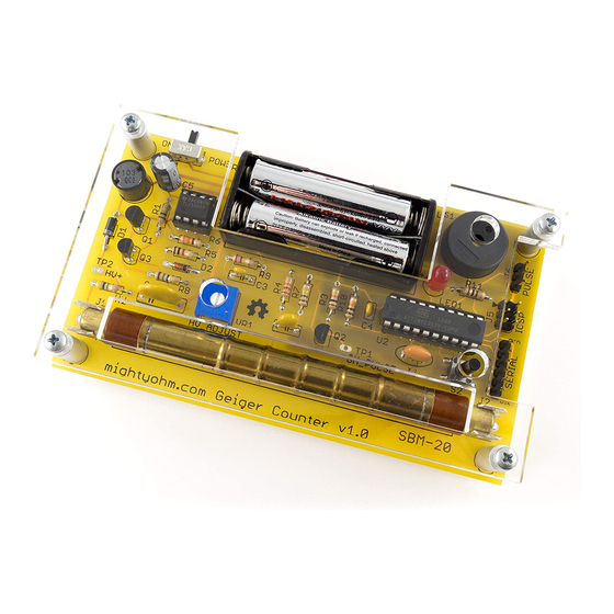
MightyOhm Geiger Counter Kit Assembly Instructions
(Updated 2019-08-01)
To build this kit, you should know how to solder. And it will be much easier if you have made other kits before.
But even if this is your first kit, do not despair! Just take your time and you'll be ok.
If you have never soldered before, Andie Nordgren, Mitch Altman, and I made a fun comic book that will teach
you how. You can find it online, translated into many languages, here:
http://mightyohm.com/soldercomic
Ok! Let's get started.
1. First, check to make sure you have all of the parts.
You should have all of the components shown in the Bill of Materials on page 7. I suggest emptying the parts
from the ESD bag onto your work surface (don't lose any!) or into a small box or bowl. Then, check each one off
the list as you sort through them.
Important note: If you purchased a case along with your Geiger counter kit (or it came as part of a bundle),
you'll want to open up the small bag of hardware that came with the case and look for a push-button with a long
(17mm) shaft. The long shaft lets you press the button after the case is installed on your kit. Solder the long
push-button last, after all of the other components. You can set aside the push-button that came with the
Geiger counter kit (the one with the short shaft), as you won't be needing it!
2. Solder the resistors.
First, take a look at the Assembly Diagram on the last page. This handy drawing shows you which resistors go
where on the circuit board. All components are mounted on the top side of the PCB.
I recommend soldering one at a time unless you know what you are doing!
The resistors can go in either way – polarity doesn't matter.
Bend the leads of each resistor straight down and push them through the holes in the board, then bend them out at
a 45-degree angle to keep the resistor from falling out.
Turn the board over, and solder each lead. Then, cut off the excess leads with your wire cutters.
In the steps that follow, you should trim all leads that stick out of the bottom of the PCB by more than 2 or 3mm.
3. Solder the diodes.
The orientation is very important, so make sure the stripe lines up with the black band shown on the board!
D1 is larger, and black with a white or silver stripe.
D2 is smaller, and reddish-orange colored, with a black stripe.
Both are labeled with the part number, although it can be hard to read.
4. Solder the slide switch (S1).
Make sure it sits flat on the board with the plastic lever sticking off the edge. I like to solder one of the leads, then
check if it's flat. If not, I reflow the solder and push it flat with my finger. (Don't leave the soldering iron on the
lead too long, or you will burn your finger!)
Be sure to solder both of the small tabs on the ends as well as the three leads.
1/8
Advertisement
Table of Contents

Summary of Contents for MightyOhm Geiger Counter
- Page 1 Important note: If you purchased a case along with your Geiger counter kit (or it came as part of a bundle), you'll want to open up the small bag of hardware that came with the case and look for a push-button with a long (17mm) shaft.
- Page 2 5. Solder capacitors C3 and C4. Both of these capacitors are very small. C4 goes next to U2 and is marked 104. It is the very tiny capacitor with narrowly spaced leads (2.5mm). C3 is marked 102 and has wider leads (5mm spacing). 6.
- Page 3 Important: If you purchased your kit with a case, use the long pushbutton that came with the case instead of the ordinary (short) one that is included with the Geiger Counter kit!!! The push-button can go in either way. No need to clip the leads on this either.
- Page 4 VR1 clockwise until you hear clicks. Once you start to hear clicks, rotate VR1 about 45 degrees more and stop. The exact adjustment is not very critical. If you got this far, congratulations! You have built a working Geiger counter! Usage Instructions If your kit isn’t working, do not dismay! Check the troubleshooting instructions on page 6.
- Page 5 Use a soft cloth (microfiber is best). Gently wipe the case clean, being careful not to scratch it. If necessary, you can remove the cover plates from the Geiger Counter and wash them in soap and warm water. Don't ever use...
- Page 6 If there is a problem with your order, send an e-mail to support@mightyohm.com. ***** WARNING ***** This Geiger Counter kit is for EDUCATIONAL PURPOSES ONLY. Don't even think about using it to monitor radiation in life-threatening situations, or in any environment where you may expose yourself to dangerous levels of radiation.
- Page 7 When you get to step 18 in the instructions, use the long pushbutton instead of the ordinary (short) one that came with your Geiger Counter kit. That way you’ll be...
- Page 8 Geiger Counter Kit – Assembly Diagram...
Need help?
Do you have a question about the Geiger Counter and is the answer not in the manual?
Questions and answers