
Subscribe to Our Youtube Channel
Summary of Contents for Genesis LGMT434
- Page 1 Masthead Masthead Repeater Repeater Installation Installation Handbook Handbook Type: LGMT434 V4.93 Issue 7. 2a BELLEVUE ROAD, FRIERN BARNET, LONDON, N11 3ER Tel: 0044 (0) 208 368 7887 Fax: 0044 (0) 208 368 3952...
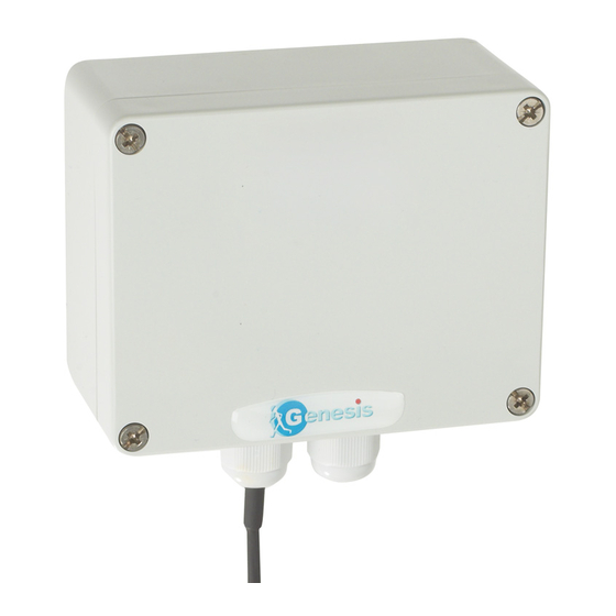
- Page 2 When the product is sealed it is water resistant to IP66. Box Contents. 1 x GENESIS Masthead / Repeater 1 x 1/4 wave antenna Copyright 2011 Luminite Electronics Ltd All rights reserved. Unauthorised duplication of this handbook by any means mechanical or electrical, is strictly prohibited without the express written permission of Luminite Electronics Ltd.
-
Page 3: Table Of Contents
Connecting to the relay control unit or compatible system. 5 Antenna connection. Code & Function switches explained. Switch setting tables. Walk Test & Repeater mode. 8 & 9 System examples using Sub Nets. Position testing. Testing the PIR’s. Types of receivers. LGMT434 Masthead Repeater Installation Handbook Page 1. -
Page 4: Introduction
Introduction The Genesis range of wireless Passive Infra Red Detectors (PIR) have been designed to meet the newest and most demanding requirements of the CCTV market. These detec- tors provide the versatility of wireless whilst meeting and surpassing the requirements needed for a BS8418 system. - Page 5 Masthead receives from PIR’s and PIR detectors transmits to walk transmit to test instrument masthead RS232 between Masthead and control unit Relay contacts or RS485 to DVR etc. Control unit Fig 1. provides alarm LGMT434 Masthead Repeater Installation Handbook Page 3.
-
Page 6: Positioning The Masthead/Repeater
25 metres maximum. Some DVR’s and transmission systems are com- patible with the Genesis system and therefore avoid the need to use the relay unit. Check the web site for the latest list of compatible products. -
Page 7: Connecting To The Relay Control Unit Or Compatible System
12 volt 300m a supply, junction box and appropriate serial lead. power adaptor (See individual products operating and Installation Instructions) 9 pin serial plug to D VR LGMT434 Masthead Repeater Installation Handbook Page 5. -
Page 8: Code & Function Switches Explained
Pagers and Walk Test Instruments do not have Sub Net Codes and will respond to the Masthead and any repeaters as long as they are the same Site Code. ( See separate Walk Test & Pager Instructions). Up to seven repeaters and one masthead may be deployed. LGMT434 Masthead Repeater Installation Handbook Page 6. -
Page 9: Switch Setting Tables
12 13 14 15 16 12 13 14 15 16 In this example Sit Code 14 has been set. The Sub Net Codes are set to the default setting of 1. SWITCHES SITE CODES LGMT434 Masthead Repeater Installation Handbook Page 7. -
Page 10: Walk Test & Repeater Mode. 8
SWITCHES SUB NET CODES TRANSMITTING SPECIALFUNCTION SWITCHES. Switches 12 through to 16 have the following functions. FUNCTION SWITCHES Reserved Relay 8 light sensor Relay 1 global output Repeater Walk Test Follow On Contacts LGMT434 Masthead Repeater Installation Handbook Page 8. - Page 11 Certain third party products are designed to work directly from the Mastheads RS232 output without the need for the LGRU16 Control Interface. Two of the most commonly used makes are listed below. Geovision Videoswitch LGMT434 Masthead Repeater Installation Handbook Page 9.
-
Page 12: System Examples Using Sub Nets
Sub Net Codes separate the system. 1 Masthead & 2 Repeaters MAST SUBNET 1 SUBNET 2 SYSTEM CONTROLLER Fig 6. SUBNET 3 LGMT434 Masthead Repeater Installation Handbook Page 10. -
Page 13: Position Testing
Screw the wall bracket to the wall using the screws and plugs provided at a height of be- tween 2 & 2.5 metres and hang the detector on it temporarily to make angle adjustments. See Fig 2 on page 5. LGMT434 Masthead Repeater Installation Handbook Page 11. -
Page 14: Testing The Pir's
Re-assemble the detector and hang it back on the wall bracket. It will not have changed position because the angle adjust screws have been locked. Fit the two M5 16 mm screws to the top and bottom of the wall plate and tighten. Page 12. LGMT434 Masthead Repeater Installation Handbook... -
Page 15: Types Of Receivers
A switch change converts the product to an 8 alarm output without tampers if required. Expansion cards are available to increase the number of alarm outputs up to a Cable gland maximum of 32. Page 13. LGMT434 Masthead Repeater Installation Handbook... - Page 16 LGMT434 Wireless PIR Detector Specification. RF input 434.525Mhz 10m/w RF output 434.525Mhz 10m/w Antenna connection Antenna 1/4 wave included RF range 1-2 Km line of sight Encoding Manchester with Rolling code Data out RS232 Settings: Baud rate 19200. 8 data bits. 1 stop bit. No Parity.
Need help?
Do you have a question about the LGMT434 and is the answer not in the manual?
Questions and answers