
Summary of Contents for ClimateWorx 11 Series
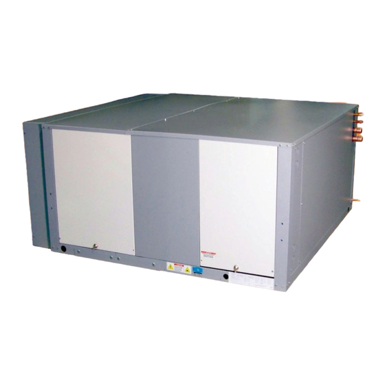
- Page 1 Series 11, Ceiling Units Installation Manual i t a S11-IM2019 14 Chelsea Lane, Brampton, Ontario, Canada L6T 3Y4...
-
Page 2: Table Of Contents
Series 11 Installation Guide Table of Contents Table of Contents ......................... 2 Site Preparation ........................3 Location Consideration ....................... 3 Positioning of Indoor units ....................3 Hanging the Unit ........................ 4 Positioning of Condensers or Condensing Units ............... 5 ... -
Page 3: Site Preparation
Series 11 Installation Guide Site Preparation In order to maximize operating efficiency and performance, the following areas should be observed at the site-planning stage: The room should be surrounded with a vapor seal to eliminate moisture migration through the building structure. Windows should be sealed and at least double-glazed to prevent sweating. All door jams should fit tightly and should not have any grilles in them. -
Page 4: Hanging The Unit
Series 11 Installation Guide Hanging the Unit Before hanging the unit, ensure the mounting surface is capable of supporting the unit’s weight. Refer to Table 1 for unit weights. Model 1 Ton 1.5 Ton 2 Ton 2.5 Ton 3 Ton 4 Ton 5 Ton (Weight lbs) -
Page 5: Positioning Of Condensers Or Condensing Units
Series 11 Installation Guide Positioning of Condensers or Condensing Units Condensing units should be located as close to the indoor unit as possible. From a security and environment standpoint, outdoor air-cooled condensing units should be installed away from public access and occupied spaces where low ambient sound level is required. -
Page 6: Positioning Of Remote Controller Unit
Series 11 Installation Guide Positioning of Remote Controller Unit The remote mounted controller should be located in an easily accessible area within reach of operating personnel. For proper operation the thermostat should be located on an inside wall. In addition its position must be at least 18”... -
Page 7: Electrical Installation
Series 11 Installation Guide Electrical Installation Power Feeding All models are fitted with a 3-terminal connection block. Single-phase power should be connected to the line side of the connection block. A ground lug is provided near the main power connection block for ground connection. -
Page 8: Piping Connections
Series 11 Installation Guide Packaged unit condenser fans The condenser fan is supplied with a 3’ length conduit/cable assembly. Attach conduit connector through the 1” hole located at the bulkhead at the top left hand corner of the electrical panel (Figure 3). Connect the two cables as per wiring diagram to the loom marked condenser fan. -
Page 9: Recommended Pipe Size For Remote Condensing Units
Series 11 Installation Guide Once the system is open, complete the work as quickly as possible to minimize ingress of moisture and dirt into the system. Always put caps on ends of tubes and parts not being worked on. To prevent scaling and oxidation inside the tubing, pass an inert gas such as nitrogen through the line while carrying out brazing, silver soldering or any other welding processes. -
Page 10: Recommended Pipe Size For Remote Condensers
Series 11 Installation Guide Recommended Pipe Size for Remote Condensers Model 1 Ton 1.5 Ton 2 Ton 2.5 Ton 3 Ton 4 Ton 5 Ton Hot Gas Line 50 ft. equivalent pipe length 1/2” 1/2” 5/8” 5/8” 5/8” 3/4” 3/4” 100 ft. -
Page 11: Fan Speed Control System
Series 11 Installation Guide 9. Stop the vacuum pump. Break the vacuum and charge the system with vapor R22/R407c (see spec label for unit refrigerant) through the discharge side of the compressor. It is a good practice to weigh the charge that is put into the system. 10. -
Page 12: Head Pressure Control System
-40°F. ClimateWorx uses a two-valve head pressure control with receiver, for factory ordered condensers. The ORI is located in the liquid drain line between the condenser and the receiver, and the ORD is located in a hot gas line bypassing the condenser. - Page 13 Series 11 Installation Guide completing the evacuation procedures as in the fan speed control system, follow the following guidelines for charging: Open the main isolator and insert the fuses for the fans, control transformers and the compressor. Close the main power and allow the compressor crankcase heater to operate for at least one hour. Connect the gauge manifold to both discharge and suction rotalock valves, with a common connection to the refrigerant cylinder.
-
Page 14: Operating The Thermostat
Series 11 Installation Guide Operating the Thermostat Setting the Current Day and Time 1. Press the CLOCK Button. The display will flash a day of the week. 2. Press the up or down arrow buttons until the current day shows. 3. - Page 15 Series 11 Installation Guide Setting your Program Times Referring to your Schedule Planner, you now will enter the times for the program periods. 1. Press the PROGRAM button. The display will flash a day of the week. 2. Press the up or down arrow buttons to select the day you wish to program. (We suggest starting with Monday.) 3.
- Page 16 Series 11 Installation Guide Temporary Override with Keyboard Locked (1 hour) (300- 225, 300- 227, 300- 229) You may change the temperature setting temporarily at any time without affecting the program, even though the keypad is locked. • Press the up or down buttons. The display will show the temperature for the first event. Press the up or down buttons again to adjust the temperature +/- 3 degrees.
-
Page 17: Dimensional Details
Series 11 Installation Guide Dimensional Details The following tables summarize the dimensional detail drawing number for Series 11 units with standard options. For units with a special option or configuration, please consult factory for details. Model Self-contained air-cooled unit S11DD101 S11DD101 S11DD101 S11DD101... -
Page 18: Appendix A: Dimensional Drawings
Series 11 Installation Guide Appendix A: Dimensional Drawings Drawing Title Drawing No. Page No. SERIES 11 – Self-contained air-cooled unit-1 to 2.5 tons S11DD101 SERIES 11 – Ducted self-contained air-cooled unit-1 to 2.5 tons S11DD152 SERIES 11 – Self-contained water/glycol-cooled unit-1 to 2.5 tons S11DD111 SERIES 11 –... - Page 19 Series 11 Installation Guide S11-IM2019...
- Page 20 Series 11 Installation Guide S11-IM2019...
- Page 21 Series 11 Installation Guide S11-IM2019...
- Page 22 Series 11 Installation Guide S11-IM2019...
- Page 23 Series 11 Installation Guide S11-IM2019...
- Page 24 Series 11 Installation Guide S11-IM2019...
- Page 25 Series 11 Installation Guide S11-IM2019...
- Page 26 Series 11 Installation Guide S11-IM2019...
- Page 27 Series 11 Installation Guide S11-IM2019...
- Page 28 Series 11 Installation Guide S11-IM2019...
- Page 29 Series 11 Installation Guide S11-IM2019...
- Page 30 Series 11 Installation Guide S11-IM2019...
- Page 31 Series 11 Installation Guide S11-IM2019...
- Page 32 Series 11 Installation Guide S11-IM2019...
-
Page 33: Appendix B: Electrical Schematic Drawings
Series 11 Installation Guide Appendix B: Electrical Schematic Drawings Drawing Title Drawing No. Electrical Schematic with standard thermostat S11EDN105 Electric Schematic Packaged Air-Cooled – General, ES9005 Electric Schematic Air-Cooled Condensing Unit – General, ES9020 Electric Schematic Air-Cooled Condenser– General, ES9030 Electric Schematic Water/ Glycol-Cooled –... - Page 34 Series 11 Installation Guide S11-IM2019...
- Page 35 Series 11 Installation Guide S11-IM2019...
- Page 36 Series 11 Installation Guide S11-IM2019...
- Page 37 Series 11 Installation Guide S11-IM2019...
- Page 38 Series 11 Installation Guide S11-IM2019...
- Page 39 Series 11 Installation Guide S11-IM2019...
- Page 40 Series 11 Installation Guide S11-IM2019...
- Page 41 Series 11 Installation Guide S11-IM2019...
- Page 42 Series 11 Installation Guide S11-IM2019...
- Page 43 Series 11 Installation Guide S11-IM2019...
- Page 44 Series 11 Installation Guide S11-IM2019...
- Page 45 Series 11 Installation Guide S11-IM2019...
- Page 46 Series 11 Installation Guide S11-IM2019...
- Page 47 Series 11 Installation Guide S11-IM2019...
-
Page 48: Appendix C: Piping Schematic Drawings
Series 11 Installation Guide Appendix C: Piping Schematic Drawings Drawing Title Drawing No. Page No. SERIES 11- Air Cooled Unit with Condenser S11DS100 SERIES 11- Air Cooled Unit with Condensing unit S11DS102 (w/ Head Pressure Control) SERIES 11- Water Cooled Unit (Self contained) S11DS200 SERIES 11- Water Cooled Unit with Condensing Unit S11DS201... - Page 49 Series 11 Installation Guide S11-IM2019...
- Page 50 Series 11 Installation Guide S11-IM2019...
- Page 51 Series 11 Installation Guide S11-IM2019...
- Page 52 Series 11 Installation Guide S11-IM2019...
- Page 53 Series 11 Installation Guide S11-IM2019...
- Page 54 Series 11 Installation Guide S11-IM2019...
- Page 55 Series 11 Installation Guide S11-IM2019...
- Page 56 Series 11 Installation Guide S11-IM2019...
- Page 57 Series 11 Installation Guide S11-IM2019...
- Page 58 Series 11 Installation Guide S11-IM2019...
- Page 59 Series 11 Installation Guide S11-IM2019...
- Page 60 Series 11 Installation Guide S11-IM2019...
- Page 61 Series 11 Installation Guide S11-IM2019...
Need help?
Do you have a question about the 11 Series and is the answer not in the manual?
Questions and answers