
Subscribe to Our Youtube Channel
Related Manuals for DFRobot DFRduino Romeo-All in one Controller V1.1


Summary of Contents for DFRobot DFRduino Romeo-All in one Controller V1.1
-
Page 1: Table Of Contents
DFRduino Romeo‐All in one Controller V1.1(SKU:DFR0004) DFRduino RoMeo V1.1 Contents 1 Introduction 2 Specification 3 DFRduino RoMeo Pinout 4 Before you start 4.1 Applying Power 4.2 Software 5 Romeo Configuration 5.1 Servo Power Select Jumper 5.2 Motor Control Pin Jumper ... -
Page 2: Introduction
Introduction RoMeo is an All-in-One microcontroller especially designed for robotics application. Benefit from Arduino open source platform, it is supported by thousands of open source codes, and can be easily expanded with most Arduino Shields. The integrated 2 way DC motor driver and wireless socket gives a much easier way to start your robotic project. -
Page 3: Before You Start
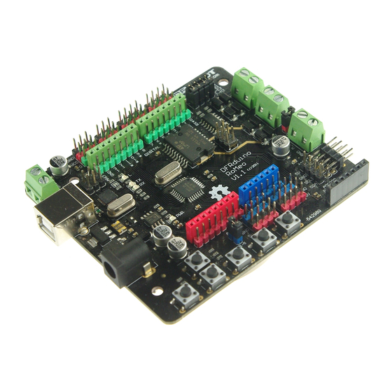
The picture above shows all of the I/O lines and Connectors on the Romeo, which includes: One Regulated Motor Power Input Terminal (6v to12v) One Unregulated Servo Power Input Terminal (you supply regulated 4v to 7.2v) One Servo input power selection jumper ... -
Page 4: Motor Control Pin Jumper
The Romeo V1.0 uses an automatic switcher for the power source selection. When the external power source has been applied, the servo will be automatically powered by the external power instead of USB power. Motor Control Pin Jumper Applying the Motor Control Pin Jumpers will allocate Pin 5,6,7,8 for motor control. Removing the jumpers will release the above Pins, and the motor controller will be disabled. - Page 5 char start_msg[15] = { "Start loop "}; adc_key_val[5] ={ 30, 150, 360, 535, 760 }; int NUM_KEYS = 5; int adc_key_in; int key=-1; int oldkey=-1; void setup() { pinMode(13, OUTPUT); //we'll use the debug LED to output a heartbeat Serial.begin(9600); /* Print that we made it here */ Serial.println(start_msg);...
-
Page 6: Dual Dc Motor Speed Control
digitalWrite(13, LOW); // Convert ADC value to key number int get_key(unsigned int input) int k; for (k = 0; k < NUM_KEYS; k++) if (input < adc_key_val[k]) return k; if (k >= NUM_KEYS) k = -1; // No valid key pressed return k;... -
Page 7: Pin Allocation
Pin Allocation "PWM Mode" Function Digital 4 Motor 1 Direction control Digital 5 Motor 1 PWM control Digital 6 Motor 2 PWM control Digital 7 Motor 2 Direction control "PLL Mode" Function Digital 4 Motor 1 Enable control Digital 5 Motor 1 Direction control Digital 6 Motor 2 Direction control Digital 7... - Page 8 The PWM DC motor control is implemented by manipulating two digital IO pins and two PWM pins. As illustrated in the diagram above (Figure 5), Pin 4,7 (7,8 for old Romeo version) are motor direction control pins, Pin 5,6 (6,9 for old Romeo version) are motor speed control pins. For previous Romeo board, the pins used to control the motor is Pin 7,8 (Direction), Pin 6,9 (Speed).
- Page 9 analogWrite (E1,a); digitalWrite(M1,LOW); analogWrite (E2,b); digitalWrite(M2,LOW); void turn_L (char a,char b) //Turn Left analogWrite (E1,a); digitalWrite(M1,LOW); analogWrite (E2,b); digitalWrite(M2,HIGH); void turn_R (char a,char b) //Turn Right analogWrite (E1,a); digitalWrite(M1,HIGH); analogWrite (E2,b); digitalWrite(M2,LOW); void setup(void) int i; for(i=4;i<=7;i++) pinMode(i, OUTPUT); Serial.begin(19200); //Set Baud Rate Serial.println("Run keyboard control");...
-
Page 10: Pll Control Mode
if(val != -1) switch(val) case 'w'://Move Forward advance (255,255); //move forward in max speed break; case 's'://Move Backward back_off (255,255); //move back in max speed break; case 'a'://Turn Left turn_L (100,100); break; case 'd'://Turn Right turn_R (100,100); break; case 'z': Serial.println("Hello");... - Page 11 Fig5: PLL Motor Control Pin Allocation Configuration Sample Code: //Standard DLL Speed control int E1 = 4; //M1 Speed Control int E2 = 7; //M2 Speed Control int M1 = 5; //M1 Direction Control int M2 = 6; //M1 Direction Control ///For previous Romeo, please use these pins.
- Page 12 digitalWrite(E1, HIGH); analogWrite(M1, (m1p)); digitalWrite(E2, HIGH); analogWrite(M2, (m2p)); void setup(void) int i; for(i=6;i<=9;i++) pinMode(i, OUTPUT); Serial.begin(19200); //Set Baud Rate void loop(void) if(Serial.available()){ char val = Serial.read(); if(val!=-1) switch(val) case 'w'://Move Forward DriveMotorP(0xff,0xff); // Max speed break; case 'x'://Move Backward DriveMotorP(0x00,0x00); ;...
- Page 13 's'://Stop DriveMotorP(0x7f,0x7f); break; Powered By DFRobot © 2008-2017...
Need help?
Do you have a question about the DFRduino Romeo-All in one Controller V1.1 and is the answer not in the manual?
Questions and answers