Microsat PLXDigi Instruction Manual, Configuration Software Manual
Aprs standalone digipeater, multipath dsp aprs decoding algorithm, weather station support, external telemetry module support, input voltage measurement, serial console for administration, easy usb-hid configuration and firmware update
Table of Contents
Advertisement
Quick Links
PLXDigi (v1.04)
APRS STANDALONE DIGIPEATER
MULTIPATH DSP APRS DECODING ALGORITHM
WEATHER STATION SUPPORT
EXTERNAL TELEMETRY MODULE SUPPORT
INPUT VOLTAGE MEASUREMENT
SERIAL CONSOLE FOR ADMINISTRATION
EASY USB-HID CONFIGURATION AND FIRMWARE UPDATE
Instruction manual
Configuration software manual
Designer: Mateusz Płociński SQ3PLX
Producer: Microsat
info@microsat.com.pl
1
Advertisement
Table of Contents

Subscribe to Our Youtube Channel
Summary of Contents for Microsat PLXDigi
- Page 1 PLXDigi (v1.04) APRS STANDALONE DIGIPEATER MULTIPATH DSP APRS DECODING ALGORITHM WEATHER STATION SUPPORT EXTERNAL TELEMETRY MODULE SUPPORT INPUT VOLTAGE MEASUREMENT SERIAL CONSOLE FOR ADMINISTRATION EASY USB-HID CONFIGURATION AND FIRMWARE UPDATE Instruction manual Configuration software manual Designer: Mateusz Płociński SQ3PLX Producer: Microsat...
-
Page 2: Table Of Contents
Table of Contents 1. Technical parameters................3 2. Device features..................4 2.1. MultiPath APRS packets decoding............4 2.2. APRS client..................4 2.3. APRS digipeater................4 2.4. Weather station support..............4 2.5. Telemetry reports................5 2.6. WXTelemetry module support (analog channels)........5 2.7. WXTelemetry module support (analog channels)........5 2.8. Firmware and configuration updates............5 3. -
Page 3: Technical Parameters
1. Technical parameters Dimensions 94x50x25 mm Weight Supply voltage 12VDC typ. (9 - 16VDC) Power consumption 50mA Operation temperature -30°C / +70°C Humidity 95% max. PC connector Mini USB-B Power, radio, telemetry connector DB-9 male Serial ports connector Mini DIN 6-pin female... -
Page 4: Device Features
2.3. APRS digipeater The main purpose of the device is receiving and sending APRS data packets via amateur radio transceiver. PLXDigi is capable of receiving an APRS packet, decoding the sender, recipent, path and information field. Then actions are performed in accordance... -
Page 5: Telemetry Reports
States of both inputs and outputs can be reported in APRS telemetry reports and outputs can also be controlled via serial port console. 2.8. Firmware and configuration updates In PLXDigi you can do all firmware and configuration updates over an USB cable connection from your PC using a simple Configurator application. -
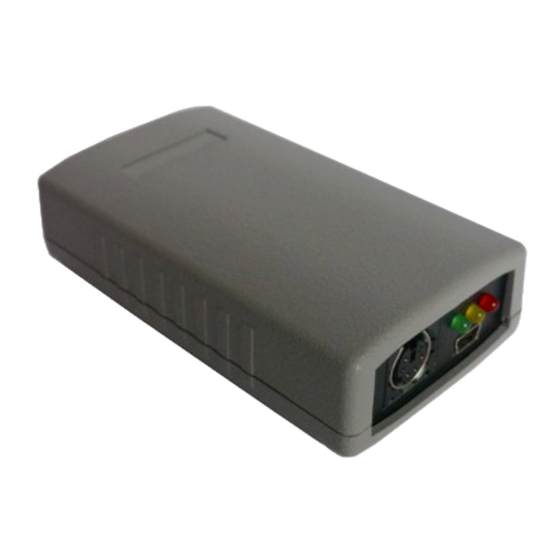
Page 6: Connectors And Device Status Leds
3. Connectors and device status leds 3.1. Front panel There are 3 leds on the front panel that show the status of device operation. The following image shows the location of front panel LEDs and connectors. Leds: Green LED - illuminates when receiving a signal from the radio (indicates the •... -
Page 7: Power, Radio, Rs-485 Connector
If you are going to use both WXTelemetry and WXBits external telemetry modules, you should connect them in a chained style: A+ and B- pair go from PLXDigi to first telemetry module, and then from first telemetry module to the second one. From a schematic point of view, both modules must be connected in parallel (A+ from PLXDigi goes to A+ of the first module, and then to A+ of the second, similarly with B-). -
Page 8: Audio Output Level Regulation
4.1. Audio output level regulation There is 1kOhm potentiometer on the device audio output. Clockwise turn increases audio output level, counter-clockwise decreases. Audio output level is regulated after production to some default value. The most suitable value is dependent on the radio used, because of various input impedance of different radios (for example, most Motorola GM-300/GM-350 radios have a strong DC voltage bias on the front audio input connector, so the output driver should be set to drive a stronger signal on the output to overcome this bias voltage). - Page 9 Our tests revealed that decoding works fine for wide range of audio input levels. Packets were decoded properly even with audio input over-driven with high-level audio signal from speaker outputs. Similarly packets were decoded even with signal level as low as 5% of the ADC conversion range...
-
Page 10: Serial Ports Connector
5. Serial ports connector In PLXDigi the MINI DIN 6pin female connector is used for RS-232 serial ports and 5V voltage output. MINI DIN 6pin connector pins description: Pin 6 – RS-232 Port 1 RXD, • Pin 4 – RS-232 Port 2 TXD, •... -
Page 11: Connecting The Weather Station
According to the manufacturer's instructions, you should press CLEAR + WIND SPEED buttons for 3 seconds to activate the "data logger". For Peet Bros weather stations you can use our prebuilt cable: “CAB01 - PLXDigi serial interface cable”. -
Page 12: Connecting To Pc
To connect to your computer, follow these steps: Disconnect PLXDigi DB-9 cable, device should be unpowered, • Connect the USB cable from your computer to PLXDigi, Red LED should start to • blink (device is now powered from USB), Now you can use PLXDigi Configurator for device configuration read/write or •... -
Page 13: Description Of Configuration Software
7.4. Configuration import/export With “Save to file” button you can export your current configuration from PLXDigi Configurator window to a file on your PC's disk drive. Similarly with “Read from file”... -
Page 14: Radio Tab
7.5. Radio Tab “Callsign” – The callsign of your station with SSID extension. This field can be up • to 6 characters long. The default SSID is 0 and allowed SSID's are between 0 and “Latitude” - north-south position of your radio station, •... -
Page 15: Digipeater Tab
“2k2 resistor” - audio output is shorted to ground via 2k2 Ohm resistor, • function used in some handheld radios for transmission enable, “Squelch level” - this a squelch level selection, with lower values usable signal • will be detected with lower signal amplitude. Default value of 1 should be the best option, “Channel busy detect”... -
Page 16: Beacons Tab
• for example WIDEn-N with N>=1 and N<=3 will forward paths: WIDE3-3, WIDE3-2, WIDE3-1, WIDE2-2, WIDE2-1, WIDE1-1, “traceable” – if Yes, PLXDigi will add its own callsign to the path, if No, it • will not do that, “active” – if not checked, current row will not be active. - Page 17 PLXDigi U=<volt>V – beacon information field, <volt> will be replaced with input • voltage reading. As you can see in the above example, PLXDigi allows to use some special strings, which are automatically replaced with corresponding values: <date> - inserts current date in DDHHMM (day/hour/minute) format, •...
-
Page 18: Weather Tab
7.8. Weather Tab “Weather station” - weather station type selection box, • “Dest” – destination field of a weather report. • “Path” – APRS path (default value of WIDE2-2 will allow your device to be • digipeated by most nearby digipeaters), if you leave this field empty, weather report will be sent without path, “RF[min]“... -
Page 19: Rtc Time Tab
“Year”, “Month”, “Day”, “Hour”, “Minute” - user-defined date and time for • PLXDigi, Internal Real Time Clock is updated when the device exits config mode and enters normal mode. To get exact time please reboot your unit to normal mode quickly after... -
Page 20: Telemetry Reports Tab
7.10. Telemetry reports Tab “Report settings” Tab: “Telemetry parameters” – this group of fields defines settings of PARM, UNIT, • EQNS, and BITS parameter packets which describe the telemetry data sent by the device, “Dest” – destination field of a telemetry parameters packet. •... - Page 21 “WXTelemetry module (analog)” - this box enables or disables WXTelemetry • module support, “WXBits module (digital)” - this box enables or disables WXBits module support. • You can find more useful information about telemetry reports format in APRS specification: http://aprs.org/doc/APRS101.PDF, page 68. Analog channels: “Analog channels”...
- Page 22 Important note: If you change “Source” field for a channel, you also need to change “Name”, “Units”, and “Coeffs” fields. Otherwise everyone elso who receive your data (including web services like aprs.fi) will not be able do decode your reports properly. Every source has its own coefficients, names and units.
- Page 23 Wxbits outputs (default state after power-up): “WXBits outputs” - this Tab defines what should be the default states for WXBits output channels. After power-up PLXDigi will constantly try to set outputs to the defined states, unless changed by the user.
-
Page 24: Serial Ports Tab
7.11. Serial ports Tab “RS-232 port 1” - allows to select function of serial port 1, • “RS-232 port 2” - allows to select function of serial port 2, • “RS-485 port” - allows to select function of RS-485 port. •...
Need help?
Do you have a question about the PLXDigi and is the answer not in the manual?
Questions and answers