
Related Manuals for Influx Technology Rebel Dash


Summary of Contents for Influx Technology Rebel Dash
- Page 1 User Documentation Rebel Dash Influx Technology WWW.INFLUXTECHNOLOGY.COM Version 1.2 19/08/2016...
-
Page 2: Table Of Contents
Creating a Configuration Ready to send to the Rebel Dash ..................6 2.2.2 Installing the Kvaser Drivers (Only required to configure the Rebel Dash through a Kvaser Device) ..... 9 2.2.3 Sending the Configuration to the Rebel Dash via the CAN bus through a Kvaser Device........12 2.2.4... -
Page 3: Rebel Dash
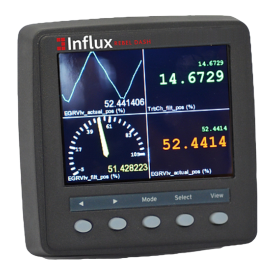
Rebel Dash The Rebel Dash is a compact, highly flexible, rugged CAN bus display. It is extremely bright making it ideal for in vehicle development tasks, where engineers need to rapidly configure it to display information to be used for various testing tasks. -
Page 4: Optional Extras Available
The Rebel Dash display is a high brightness QVGA (320x240pixels) colour display that is viewable in full sunlight on a 3.5inch colour display with integrated input and output features. -
Page 5: The Rebel Dash Software
2.1 Installing the Rebel Dash Config Software STEP 1 To begin the installation for the software, double-click on the Rebel Dash Config setup icon to proceed. STEP 2 A pop-up will appear for the verification of install the software. Click ‘Run’ to confirm the installation of the software. -
Page 6: Configuring The Rebel Dash Using The Rebel Dash Software
2.2 Configuring the Rebel Dash using the Rebel Dash Software The Rebel Dash software provides a software that is easy for the user to configure on the Rebel Dash, just follow the simple steps below and the device will be ready to collect the data. This is used when you wish to configure the Dash to display data from a vehicles CAN Bus or from the K-Box instrumentation (or both), it could also be used to display data from any other device that broadcasts simple CAN Messages on a CAN bus e.g. - Page 7 >> button. Step 5 To choose the signal(s) to be logged onto the Rebel Dash, click on an identifier to select it, a list of available signal(s) will appear under the ‘Signal’ panel.
- Page 8 Step 7 The user can then click on the ‘>’ button to add the signal to the configuration or the ‘<’ button to undo the process. Step 8 Repeat Steps 5 to 8 until all the signals that are desired in the configuration have been added.
-
Page 9: Installing The Kvaser Drivers (Only Required To Configure The Rebel Dash Through A Kvaser Device)
2.2.2 Installing the Kvaser Drivers (Only required to configure the Rebel Dash through a Kvaser Device) Step 1 Download the Kavaser Drivers for Windows, they are located at: https://www.kvaser.com/downloads/ Step 2 Run kvaser_drivers_setup.exe. Step 3 Click Next to start the Installation. - Page 10 Step 4 Click Next after viewing the documentation (optional). Step 5 Select the item(s) you wish to install, you will need to install at least the Drivers.
- Page 11 Step 6 Choose or confirm the location that you wish to install the drivers to. Step 7 The Drivers will be installed, click close once the process is complete.
-
Page 12: Sending The Configuration To The Rebel Dash Via The Can Bus Through A Kvaser Device
Select the baud rate by pressing on the down arrow button on the baud rate option. The baud rate needs to be adjusted to be the same as the baud rate that the Rebel Dash device is using in order for the interface to work. - Page 13 Step 9 Click on the ‘Conf CAN’ icon to send the Configuration to the Rebel Dash. The application will show the data are being transferred to the Rebel Dash and will notify once the Rebel Dash has been configured. Note •...
-
Page 14: Sending The Configuration To The Rebel Dash Via Usb Stick
Insert a FAT-32 formatted USB stick into the PC or Laptop. Warning • The USB stick must be compatible with the Rebel Dash and physically small enough to fit into the USB socket on the Rebel Dash, Influx Technology can provide USB sticks that are suitable, if you need one simply contact Influx Technology. - Page 15 Wait while the following message is displayed, making sure that the power is not removed and also that the USB stick is not removed Step 7 When you see the following message please remove the USB stick. Step 8 Wait for the Rebel Dash to reboot for few seconds and it will be ready to be used.
-
Page 16: Configuring The Rebel Dash Using Dialog
Configuring the Rebel Dash using DiaLog If you are using the Dash to display data from a Rebel CT or LT Logger you will use DiaLog to configure the Dash. You should be familiar with using DiaLog to configure the Logger and have the Project that you wish to display items from created... - Page 17 Step 2 Once the Edit Configuration window is displayed, Click on the ‘Settings’ Tab and put a Check mark in Aux Power On. Step 3 Then Click OK…...
- Page 18 Step 4 The configuration must contain CAN 1 (MS) so that the Dash connected on CAN 1 can be configured automatically, check if it is there. Step 5 If CAN 1 (MS) it not already there click + New Bus to add it Step 6 Select CAN 1 (MS) and press OK.
- Page 19 Step 7 Select Auto Baud Rate and press OK. Step 8 To send the configuration to the Logger, right click on the Project and choose “Send Configuration to the Logger”.
- Page 20 Once the Dash is on we can proceed to configuring the Logger to output the desired information on the CAN bus and creating a Rebel Dash Configuration to allow it to be selected for display. Step 9 Selecting the Items to be accessible on the Rebel Dash by right clicking on the Project and choose “New/Edit Output Signal”.
- Page 21 Step 10 Click ‘New Ident’ to set up the CAN Identifier you wish to broadcast on. Step 11 As an example we will choose CAN Identifier 600 and we will broadcast every 100ms. You may choose any CAN Identifier you wish to use...
- Page 22 Step 12 Once you have added the Ident, you can add the Items you wish to broadcast by clicking ‘Add Item’.
- Page 23 Now click Set Output CAN, you will need to choose CAN MS in order to select CAN 1 that is connected to the AUX connector of the multi connect cable that if you are attaching the Rebel Dash to that connector.
- Page 24 Optional Steps If you want to create a Rebel Dash configuration that can be used to configure the Dash via USB (Not required as the Dash will be configured when you send the configuration to the Logger, if it is attached) Step 16 You can press ‘Export’...
- Page 25 Step 19 Press OK again to update the configuration. Step 20 Right click on the Project and choose “Send Configuration to the Logger”. This will also update the dash if it is attached and on. Alternatively once the Dash is on, proceed to configuring the Dash with the USB Stick created in the optional step, Simply insert the stick and the Dash will notify you that the configuration file has been copied, once you remove the USB stick the Dash will reboot and be avaiable to display your signals.
-
Page 26: Using The Rebel Dash To Display The Signals
Once configured via the configuration program or Dialog (or not at all if you only want to use the CAN viewer) you are ready to use the Rebel Dash. 4.1 Config Menu The Config Menu of Rebel Dash device which allows the user to change the setting of the device is accessed by holding the View Key for 1 second. -
Page 27: Can Viewer
4.1.1 CAN Viewer The CAN viewer allows user to view the CAN messages on the CAN bus which are decoded in hexadecimal format along with the identifier and the time stamp. To pause the view, just pressing the ‘<’ button to pause the reading. Then, press the ‘<’ button to scroll up and the ‘>’ button to scroll down. -
Page 28: Changing Between Signals
4.2 Changing between Signals To change the signal to be viewed on the display, just press the ‘<’ and ‘>’ arrow buttons. To change the mode in which to display the signal e.g. from Meter Display Mode to Binary Display Mode press mode. -
Page 29: Meter Display
To change the viewer mode on the Rebel Dash, just press the “Mode” button to toggle the option. 4.2.2 Meter Display To change the signal to be viewed on the display, just press the ‘<’ and ‘>’ arrow buttons. To change the mode in which to display the signal i.e. -
Page 30: Changing The Display Mode
4.3 Changing the Display Mode To change the display option on the Rebel Dash, just press on the “View” button to toggle the option. 4.3.1 Single Display To view a signal in a single display. To change to Multi Display Mode press View for a short time. -
Page 31: Updating The Firmware In The Rebel Dash
Updating the Firmware in the Rebel Dash Step 1 To update the Rebel Dash insert an empty USB stick that is compatible with the Rebel Dash into your PC. Step 2 Right Click the file C:\Program Files (x86)\Influx Technology\Rebel Dash Config\firmware\RebelDash1.04.zip and select Extract All…... - Page 32 WinZip then you will need to move them to the correct location. Step 5 Safely Remove the USB Stick From your PC. Step 6 Insert the Stick into the Rebel Dash; You will then see: on its screen you will see: Step 7...
-
Page 33: Appendix 1 Pinout Of The Rebel Dash Cable
Pinout of the Rebel Dash Cable The Rebel Dash Cable has been designed with CiA® 102 pinout for the CAN bus and power in order to make connecting the device as simple as possible. The Standard Display Cable may be connected directly to DB9 connectors with CiA® 102 pinout, CAN and power is required to make the device power up and display data. -
Page 34: Appendix 2 Pinout Of The Obd2 To Db9 Cable
Appendix 2 Pinout of the OBD2 to DB9 Cable The Standard Display Cable may be connected to the optional DB9 to OBD2 Cable for direct connection to the Diagnostics CAN bus and power in a vehicle the pinout of that cable is as follows: Pin Function OBD2 Pin Function... -
Page 35: Appendix 3 Pinout Of The Multi Connect Cable
The Standard Display Cable may be connected to the AUX cable of the multi connect cable to allow it to be connected to the Rebel CT or LT Loggers the pinout is as follows: AUX (The port of the Multi Connect Cable that is normally used with the Rebel Dash) Pin Function... - Page 36 Digital/Analog (This Connector is used to connect Digital and Analog signals to the Logger) DB15 Pin Function Pin 2 Digital I/0 1 Pin 3 +4.5V Instrumentation Pin 4 Ground Pin 6 Analog Ground Pin 7 Ain1 inst Pin 8 Ain3 inst Pin 9 Digital I/0 0 Pin 10...
- Page 37 Pin 6 CAN 1 (MS) L Pin 7 CAN 0 (HS) L Pin 8 K-Line Pin 9 4.5-36V (10-32V is required for the Rebel Dash to operate) Pin 10 +4.5V instrumentation Pin 11 Digital I/O 2 Pin 12 Digital I/O 0...
-
Page 38: Appendix 4 Technical Specifications
Appendix 4 Technical Specifications:...
Need help?
Do you have a question about the Rebel Dash and is the answer not in the manual?
Questions and answers