Table of Contents
Advertisement
Quick Links
Advertisement
Table of Contents

Subscribe to Our Youtube Channel
Summary of Contents for JETI model Central Box
- Page 1 ® User Manual...
-
Page 2: Table Of Contents
2.1.1 Central Box 210 ............... 5EN 2.1.2 Central Box 220 ............... 6EN 2.2. Central Box 100 ............... 8 EN 2.3 Magnetic switch ( Central Box 210/220 ) ......9 EN 3. Connection ..................10 EN 3.1 Power supply of Central Box 210/220 ........ 10 EN 3.2 Power supply of Central Box 100 ......... - Page 3 5.7 Reset to factory settings ............34 EN 6. Firmware update ................35 EN 7. Safety precautions for working with magnets ....36 EN 8. Technical specifications of the Central Box ......37 EN 9. Warranty, service and the technical support ....... 38 EN 2 EN...
-
Page 4: Introduction
(PPM, EX Bus, S.BUS) output can be connected to the Central Box 210 and 220. With JETI DC/DS transmitter, the full potential of the Central Box can be used, such as an easy way to configure the Central Box, EX telemetry, and very fast servo response. -
Page 5: Attributes
Each output is individually configurable (channel assignment, trim, reverse, ATV) 1.1.2 Central Box 210/220 • Central Box 210 has unreduced power for each servo (without fuses) • Central Box 220 has overload protection on each channel (4 outputs for high-torque servos and 11 outputs for standard servos) •... -
Page 6: Description
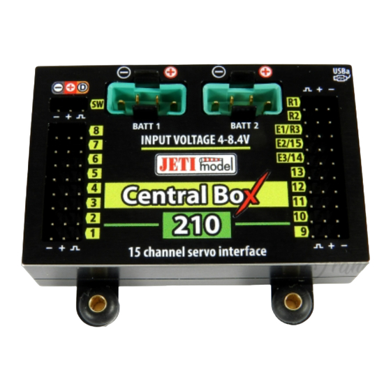
2 Description 2.1 Central Box 210/220 2.1.1 Central Box 210 • Central Box 210 has 15 outputs for servos (support of DITEX telemetry servos). • Each of the outputs can be operated in these modes: - servo output (default setting) -
Page 7: Central Box 220
BEC, etc., to power the servos and receivers connected to the Central Box. 2.1.2 Central Box 220 • Central Box 220 has 15 outputs for servos (support of DITEX telemetry servos) with individual overload protection. Each of the outputs can be operated in these modes:... - Page 8 • SW - input is reserved for connecting a magnetic switch or RC switch (optional accessories). • BATT1 and BATT2 – MPX connectors for connecting batteries or a BEC, etc., to power the servos and receivers connected to the Central Box. RC Switch 15 channel protected servo interface Magnetic Switch Fig.
-
Page 9: Central Box 100
2.2 Central Box 100 The Central Box 100 has 8 servo outputs with individual overload protection , labeled with numbers for the output. Each of the outputs can be operated in these modes: • servo output • digital input •... -
Page 10: Magnetic Switch ( Central Box 210/220 )
Central Box 210/220 by the interconnection cable from normal Master port on the magnetic switch to a slot labeled "SW" on the Central Box 210/220. To turn on the Central Box using the magnetic switch it is necessary to hold the... -
Page 11: Connection
Central Box and these other components. Central Box 100, Central Box 210 and 220 do not contain circuitry to stabilize or regulate voltage to the servos. The level of the input voltage is equal to the level of (output) supply voltage level to the servos. - Page 12 This allows you to use batteries of different capacity, number of cells, and chemistry type. If the power for the Central Box 210/220 is provided only from one battery, it can be connected via BATT1 or BATT2 input.
-
Page 13: Power Supply Of Central Box 100
Voltage 8.4V Ext. 15 channel protected servo interface Fig. 5: Example of the Central Box powered for use with HIGH Voltage servos 3.2 Power supply of Central Box 100 The Central Box 100 can be powered from batteries which are directly connected, via a BEC, via a regulator or from another Central Box. - Page 14 Ext. 8 channel servo interface Out/In Ext. Fig. 7: Example of the Central Box 100 powered for use with HIGH Voltage servos It is not recommended to supply power to the Caution: Central Box through the outputs for servos labeled Y1-8, for sensors labeled Ext or for receivers labeled Rx1-2.
-
Page 15: Overload Protection Of Servos
3.3 Overload protection of servos (Central Box 100/220) The Central Box 100 and Central Box 220 has an overload protection circuit on every servo output. In case of an overload, the affected servo output is disconnected from the power supply while the remaining servo outputs are still powered. -
Page 16: Connecting Central Box - Ex Bus
- by DC/DS transmitter via Device Explorer (EX Bus) see „Fig. 9" 3.4.2 Connecting Central Box 100 Receivers can be connected to the Central Box 100 using the Rx1 and Rx2 inputs. The serial link of the receivers (Ext.) has to be set to EX Bus. - Page 17 - by DC/DS transmitter via Device Explorer (EX Bus) see „Fig.10" Rsat2 (R2) Ext. RC Switch Magnetic Switch Rsat2 (R1) Input Voltage Ext. Jetibox/Sensor SERVO/Sensor SERVO 15 channel protected servo interface Fig. 9: Block diagram of Central Box 210/220 connection - EX Bus variant 16 EN...
-
Page 18: Alternative Functions - Digital Input
8 channel servo interface Ext. Jetibox/Sensor Fig. 10: Block diagram of Central Box 100 connection - EX Bus variant 3.5 Alternative functions – digital input Using the pin as an input is useful for simple feedback, without the use of telemetry sensors. -
Page 19: Alternative Functions - Digital Output
In the digital output mode, no control servo pulses are generated for that particular pin. With digital outputs, the Central Box is even able to control devices that do not use servo impulse as their input, e.g. lights, sound generators, etc. -
Page 20: Out/In Pin (Central Box 100)
3.7 OUT/IN pin (Central Box 100) The Central Box 100 is supplied with a special output for switching loads with a maximum current of 100mA. The pin can be connected so that the load connected to it will be powered from a common supply of the Central Box 100, see the picture 13. - Page 21 Picture 15 depicts OUT/IN pin in the input function. INPUT Internal wiring OUT/IN Typ. Ext. OUT/IN Fig. 15 Configuration of pin OUT/IN as INPUT 20 EN...
-
Page 22: Configuration Via Jetibox
4 Configuration via JETIBOX The JETIBOX terminal can be used for parameter setting and retrieving data. After connecting to the Central Box (CB100 output Ext1 or CB210/220 output E1/R3), a startup screen appears that contains identification of the device in the first line of the JETIBOX display. -
Page 23: Actual Values
4.2 Minimum / Maximum values *CENTRAL BOX*: MIN / MAX – by pushing the D button (down arrow) you select a display of extreme voltage, current, temperature, and status of the receiver, which occurred during the operation. -
Page 24: Setting
R3: what percentage of the total operating time was the signal from the third receiver available to the Central Box 210/220 • Over-I Monitor (CB100/220) - indication of servo output during the operating time of the Central Box; (-) output is fine (x) the output is overloaded 4.3 Setting *CENTRAL BOX*: SETTING –... - Page 25 80ms the Central Box switches to another active receiver. - Mixing – The Central Box combines data from all active receiver inputs and uses it for servos on the packet-by-packet basis. This strategy is available only if receivers are connected to the Central Box via EX Bus.
-
Page 26: Out Pin Set
4.4 Out Pin Set *CENTRAL BOX*: Out Pin Set – pushing the D button (down arrow) moves you to basic settings of particular outputs of the Central Box. • Set Output pin -selection of the slot that will be used for the following settings. -
Page 27: Alarms
0. Otherwise the output is set to logical 1. OppositeDirection Y- reversing output direction FailSafe.Y- setup of the Central Box behavior in case of the signal loss repeat – repeating the last valid figure on the output log.1 –... -
Page 28: Service Information
Central Box overheating Temperature goes above 70/90°C for Central Box 220/210. • Alarm Rx – the alarm is generated if the Central Box does not receive any information about valid servo positions from the R1 input for a period longer than 1s 4.6 Service information... -
Page 29: Configuration Via The Dc/Ds Transmitter
- Receiver firmware version Duplex (Rx FW 3.24 or REX FW 1.14) and newer (with setting Output mode->EX Bus) - The receiver must be connected to the Central Box via EX Bus - Transmitter firmware version 5.01 and newer + the device profile (CBOX100.bin, CBOX210.bin and CBOX220.bin) recorded... -
Page 30: Settings
This strategy is available only if receivers are connected to the Central Box via EX Bus. Another type of serial communication is not supported. Mixing strategy is not suitable for a combination of Assist receiver with standard receiver(s). -
Page 31: Alternate Functions Of Pins
5.2 Alternate functions of pins Overall setting of alternate functions for individual pins of the Central Box. Possible settings: - Servo out.- servo control signal will be generated for the pin - Digi. output –log. 1 or log. 0 is generated on the output according to the position of the assigned channel and according to the trigger level. -
Page 32: Servo Fail-Safe
Central Box outputs at signal loss. If you activate the Fail-Safe function, the behavior of the Central Box output corresponds with the setting of individual outputs (Out off, Hold, Fail-Safe). -
Page 33: Servo Output Mapping
The Fail-Safe position can be immediately applied to the Central Box output if the cursor is on the „Value" menu item and you push the F4 function key. „F4 (Apply)". Fig. 20: Device Explorer-Fail Safe 5.4 Servo Output Mapping • Servo No. -
Page 34: Telemetry
• Shorted outputs No.(CB100 and CB220 only) – actual number of overloaded outputs • Voltage – actual voltage of individual outputs of the Central Box • Current – actual current drawn from the battery • Capacity – capacity taken from the batteries Fig. -
Page 35: Reset To Factory Settings
For description of individual items, see the chapter Minimum/Maximum values. Fig. 23: Device Explorer-Telemetry Min/Max 5.7 Reset to factory settings • Reset to factory settings – reset to factory setting of the Central Box (you can find it in the general settings) 34 EN... -
Page 36: Firmware Update
Firmware update Central Box allows firmware update via a PC. The update is performed using the JETI USBa (USB adapter). The procedure is as shown below: On the manufacturer internet pages (www.jetimodel.com), under „Downloads", you will find an Jeti Studio program with the most recent firmware. -
Page 37: Safety Precautions For Working With Magnets
8 channel servo interface USBa Safety precautions for working with magnets Because the Central Box is put into operation via magnet, it is necessary to follow safety precautions for handling magnets. The magnet is mounted in a hard aluminum carrier. -
Page 38: Technical Specifications Of The Central Box
Technical specifications of the Central Box Technical specifications of the Central Box Recommended input voltage 4 – 8.4 V Number of connectable accu cells 2 LiXX Continuous current 10 A Output pulse current 90 A Number of servo outputs up to 8 Operating temperature - 20°C up to +75°C... -
Page 39: Warranty, Service And The Technical Support
You can contact either your dealer, or directly the manufacturer JETI model s.r.o.. For further information see our webpages www.jetimodel.com. We wish you sucessful flying with the products of: JETI model s.r.o. Příbor, www.jetimodel.com 38 EN... - Page 40 Object of the declaration: Products: Servo interface Trade name: Central Box Model: Central Box 100, 210, 220 Country of origin: Czech republic The object of declaration described above is in conformity with the requirements of the folowing EU legislations and harmonized standards: ČSN EN 61000-6-1:2007, ČSN EN 61000-6-3:2007+A1:20011...
- Page 41 40 EN...
- Page 42 JETI model s.r.o. Lomená 1530, 742 58 Příbor Czech Republic www.jetimodel.com www.jetimodel.de info@jetimodel.cz...
Need help?
Do you have a question about the Central Box and is the answer not in the manual?
Questions and answers