Table of Contents
Advertisement
Quick Links
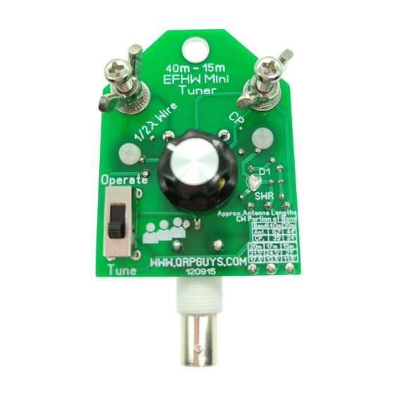
QRPGuys EFHW 40m-15m Mini Tuner Assembly Manual
First, familiarize yourself with the parts and check for all the components. If a part is missing, please
contact us and we will send one. You must use
qrpguys.parts@gmail.com
to request a part.
Parts List
1 – QRPGuys EFHW Tuner PCB
1 – Slide switch – DPDT
1 – C1, polyvaricon, w/shaft and mtg. hardware, 1 long, 2 short metric screws, and nylon spacer 3/8"L
1 - T50-6 toroid core (yellow)
1 – FT37-43 toroid core (black)
1 – 48" of 26AWG magnet wire for the toroids
1 – Medium size control knob
1 - BNC PCB connector
2 – 4mm x 30mm long SS Phillips screw
4 – 4mm nut
2 – 4mm lock washer
2 – 4mm SS wing nut
2 – 4-40 x 1/2" long nylon screw
2 – 4-40 nylon nut
2 – 3/8" diameter #4 nylon washer
2 - 1/8"diameter x 1/2" long vinyl Caplug
1 – C2, .1uF mono capacitor, marked 104
1 – D1, Red LED w/clear lens
1 – R4, 470 ohm resistor (yellow-violet-brown-gold)
3 – R1-3, 51 ohm 2W power resistor (green-brown-black-gold, or value is printed on the component)
1 – D2, 1N4148 signal diode, sm. glass, w/black band on one end
1 – 8mm round self-adhesive rubber foot
1
8
Page
of
efhw_tuner_assy_090110.pdf
Advertisement
Table of Contents

Related Manuals for QRPGuys EFHW

Summary of Contents for QRPGuys EFHW
- Page 1 QRPGuys EFHW 40m-15m Mini Tuner Assembly Manual First, familiarize yourself with the parts and check for all the components. If a part is missing, please contact us and we will send one. You must use qrpguys.parts@gmail.com to request a part.
- Page 2 We will assemble the smallest components first. Not all components are on the same side of the board. Please note the graphic below, as to which is front and back of the PCB. Install D1, the clear lens LED on the “FRONT”...
- Page 3 Next, refer to the sketch below and install the following components on the “BACK” side of the board. Do not elevate the components. Install C2, .1uF, marked 104 Install D2, 1N4148 signal diode, observing the black polarity band (cathode) location as shown above.
- Page 4 For L2, use the FT37-43 (black) core and 24” of the supplied magnet wire. You are winding a total of turns, with a tap at turns from the beginning of winding. Remember, every time the wire goes through the center of the core, it counts as one turn. Use the same twisted technique for the tap as L1.
- Page 5 Secure L1 to the bottom side of the board using one of the 4-40 nylon screws, nylon washer, and nylon nut, as shown below. Tighten enough to secure and protect the toroid, but do not over tighten. Solder L2 where indicated on the PCB, and centered on the screw hole. You will notice the tap hole is indicated, and is slightly larger in diameter to accept the double twisted wire.
- Page 6 Adjust the two trimmer caps on the back of each poly-varicon to their minimum value as shown below. Install the polyvaricon capacitor on the “BACK” side of the board by carefully bending the three leads towards the shaft end of the capacitor. Feed the three leads through the board and secure it with the two short metric Phillips screws from the top.
- Page 7 Install the nylon spacer shaft, retaining screw, and control knob onto the polyvaricon as shown. This completes the electrical and mechanical assembly. Schematic: Tuner usage The tuner is rated at 5W CW, 10 watts PEP max. and incorporates the N7VE LED absorption bridge circuit for sensing SWR.
- Page 8 An “L” configuration may work well if you can get the part of the wire from the tuner up to the tree as vertical as possible. If you use a counterpoise try to lay it out in a straight line, when possible. Additionally, after the antenna is tuned up, keeping the bridge in the circuit (Tune position) will reduce the power by a factor of four to a matched antenna.
Need help?
Do you have a question about the EFHW and is the answer not in the manual?
Questions and answers