
Subscribe to Our Youtube Channel
Related Manuals for Freenove Ultimate Starter Kit

Summary of Contents for Freenove Ultimate Starter Kit
- Page 1 Free your innovation Freenove is an open-source electronics platform. www.freenove.com...
- Page 2 Warning When you purchase or use Freenove Ultimate Starter Kit for Raspberry Pi, please note the following: This product contains small parts. Swallowing or improper operation can cause serious infections and death. Seek immediate medical attention when the accident happened.
- Page 3 You can download the sketches and references used in this product in the following websites: http://www.freenove.com https://github.com/freenove If you have any difficulties, you can send email to technical support for help. The references for this product is named Freenove Ultimate Starter Kit for Raspberry Pi, which includes the following folders and files: Datasheet Datasheet of electronic components and modules ...
-
Page 4: Table Of Contents
Preface www.freenove.com █ Contents Contents ..................4 Preface ..................7 Raspberry Pi ................8 Install the System ..............15 Component List..................................15 Optional Components ................................17 Raspbian System..................................19 Remote desktop & VNC ................................. 22 Chapter 0 Preparation ............32 Linux Command.................................. - Page 5 █ www.freenove.com Preface Project 6.1 Doorbell.................................. 88 Project 6.2 Alertor ..................................94 Chapter 7 AD/DA Converter ..........99 Project 7.1 Read the Voltage of Potentiometer ......................99 Chapter 8 Potentiometer & LED ......... 110 Project 8.1 Soft Light................................110 Chapter 9 Potentiometer & RGBLED ......115 Project 9.1 Colorful Light ..............................
- Page 6 Preface www.freenove.com █ Project 20.1 I2C LCD1602..............................220 Chapter 21 Hygrothermograph DHT11....230 Project 21.1 Hygrothermograph............................230 Chapter 22 Matrix Keypad ..........237 Project 22.1 Matrix Keypad..............................237 Chapter 23 Infrared Motion Sensor......247 Project 23.1 Sense LED................................247 Chapter 24 Ultrasonic Ranging........253 Project 24.1 Ultrasonic Ranging............................
-
Page 7: Preface
█ www.freenove.com Preface Preface If you want to become a maker, you may have heard of Raspberry Pi or Arduino before. If not, it doesn’t matter. Through referencing this tutorial, you can be relaxed in using Raspberry Pi to create dozens of electronical interesting projects, and gradually realize the fun of using Raspberry Pi to complete creative works. -
Page 8: Raspberry Pi
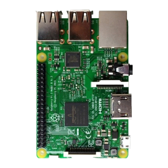
Raspberry Pi www.freenove.com █ Raspberry Pi Raspberry Pi (called RPi, RPI, RasPi, the text these words will be used alternately later), a micro-computer with size of a card, quickly swept the world since its debut. It is widely used in desktop workstation, media center, smart home, robots, and even the servers, etc. - Page 9 █ www.freenove.com Raspberry Pi Practicality picture of Raspberry Pi 3 Model B: Model diagram of Raspberry Pi 3 Model B: Practicality picture of Raspberry Pi 2 Model B: Model diagram of Raspberry Pi 2 Model B: support@freenove.com █...
- Page 10 Raspberry Pi www.freenove.com █ Practicality picture of Raspberry Pi 1 Model B+: Model diagram of Raspberry Pi 1 Model B+: █ support@freenove.com...
- Page 11 █ www.freenove.com Raspberry Pi Practicality picture of Raspberry Pi 3 Model A+: Model diagram of Raspberry Pi 3 Model A+: Practicality picture of Raspberry Pi 1 Model A+: Model diagram of Raspberry Pi 1 Model A+: support@freenove.com █...
- Page 12 Raspberry Pi www.freenove.com █ Practicality picture of Raspberry Pi Zero W: Model diagram of Raspberry Pi Zero W: Practicality picture of Raspberry Pi Zero: Model diagram of Raspberry Pi Zero: █ support@freenove.com...
- Page 13 █ www.freenove.com Raspberry Pi Hardware interface diagram of RPi 3B+/3B/2B/1B+ is shown below: GPIO Connector Connector Display Connector Ethernet Power Connector Connector HDMI Camera Audio Connector Connector Connector Hardware interface diagram of RPi 3A+/A+ is shown below: GPIO Connector Connector...
- Page 14 Raspberry Pi www.freenove.com █ Hardware interface diagram of RPi Zero/Zero W is shown below: GPIO Connector Camera Connector Power HDMI Connector Connector Connector █ support@freenove.com...
-
Page 15: Install The System
█ www.freenove.com Install the System Install the System Firstly, install a system for your RPi. Component List Required Components Any Raspberry Pi 5V/2.5A Power Adapter. Different versions of Raspberry Pi have different power requirements. Micro USB Cable x1 Micro SD Card(TF Card)x1, Card Reader x1... - Page 16 Install the System www.freenove.com █ Power requirement of different versions of Raspberry Pi is shown in following table: Product Recommended Maximum total USB Typical bare-board active PSU current peripheral current draw current consumption capacity Raspberry Pi 700mA 500mA 200mA Model A Raspberry Pi 1.2A...
-
Page 17: Optional Components
█ www.freenove.com Install the System Optional Components Under normal circumstances, there are two ways to login to Raspberry Pi: using independent monitor, or remote desktop to share a monitor with your PC. Required Accessories for Monitor If you want to use independent monitor, mouse and keyboard, you also need the following accessories. - Page 18 Install the System www.freenove.com █ Required Accessories for Remote Desktop If you don't have an independent monitor, or you want to use a remote desktop, first you need to login to Raspberry Pi through SSH, then open the VNC or RDP service. So you need the following accessories.
-
Page 19: Raspbian System
█ www.freenove.com Install the System Raspbian System Tool and System image Software Tool A tool Disk Imager Win32 is required to write system. You can download and install it through visiting the web site: https://sourceforge.net/projects/win32diskimager/ Selecting System Visit RPi official website (https://www.RaspberryPi.org/), click “Downloads” and choose to download “RASPBIAN”. - Page 20 Install the System www.freenove.com █ Write System to Micro SD Card First, put your Micro SD card into card reader and connect it to USB port of PC. Then open Win32 disk imager, choose the correct letter of your Micro SD Card (here is “J”), open the extracted “.img” file and then click the "Write".
- Page 21 █ www.freenove.com Install the System Start Raspberry Pi If you don’t have a spare monitor, please jumper to next section. If you have a spare monitor, please follow steps in this section. After the system is written successfully, take out Micro SD Card and put it into the card slot of RPi. Then connect RPi to screen through the HDMI, to mouse and keyboard through the USB port, to network cable through the network card interface and to the power supply.
-
Page 22: Remote Desktop & Vnc
Install the System www.freenove.com █ Remote desktop & VNC If you don't have a spare display, mouse and keyboard for your RPi, you can use a remote desktop to share a display, keyboard, and mouse with your PC. Below is how to use remote desktop to control RPi under the Windows operating system. - Page 23 █ www.freenove.com Install the System Then use cable to connect your RPi to the routers of your PC LAN, to ensure your PC and your RPi in the same LAN. Then put the system Micro SD Card prepared before into the slot of the RPi and turn on the power supply waiting for starting RPi.
- Page 24 Install the System www.freenove.com █ Then there will be a login interface (RPi default user name: pi; the password: raspberry). When you enter the password, there will be no display on the screen. This is normal. After the correct output, press “Enter” to confirm.
- Page 25 █ www.freenove.com Install the System Remote Desktop Connection & xrdp If you want to use built-in Remote Desktop Connection under Windows, you need install xrdp service on Raspberry Pi. Next, install a xrdp service, an open source remote desktop protocol(rdp) server, for RPi. Type the following...
- Page 26 Install the System www.freenove.com █ Login to Windows remote desktop Use "WIN+R" or search function, open the remote desktop application "mstsc.exe" under Windows, enter the IP address of RPi and then click “Connect”. Later, there will be xrdp login screen. Enter the user name and password of RPi (RPi default user name: pi;...
- Page 27 █ www.freenove.com Install the System Later, you can enter the RPi desktop system. Here, you have successfully used the remote desktop login to RPi. support@freenove.com █...
- Page 28 Install the System www.freenove.com █ VNC Viewer & VNC Type the following command. And select 5 Interfacing OptionsP3 VNC YesOKFinish. Here Raspberry Pi may need be restarted, and choose ok. Then open VNC interface. sudo raspi-config █ support@freenove.com...
- Page 29 █ www.freenove.com Install the System Then download and install VNC Viewer by click following link: https://www.realvnc.com/en/connect/download/viewer/windows/ After installation is completed, open VNC Viewer. And click File New Connection. Then the interface is shown below. Enter ip address of your Raspberry Pi and fill in a Name. And click OK.
- Page 30 Install the System www.freenove.com █ Here, you have logged in to Raspberry Pi successfully by using VNC Viewer If you think resolution ratio is not OK, you can set a proper resolution ratio on set interface of Raspberry Pi. sudo raspi-config Select 7 Advanced OptionsA5 Resolutionproper resolution ratio(set by yourself)OK.
- Page 31 █ www.freenove.com Install the System Here, you have logged in to Raspberry Pi successfully by using VNC Viewer and operated proper setting. Then continue to do some preparation work: install a GPIO library wiringPi for your RPi. Wi-Fi Raspberry Pi 3B+/3B integrates a Wi-Fi adaptor. You can use it to connect to your Wi-Fi. Then you can use the wireless remote desktop to control your RPi.
-
Page 32: Chapter 0 Preparation
Chapter 0 Preparation www.freenove.com █ Chapter 0 Preparation Why is “Chapter 0”? Because in the program code, all the counts are starting from 0. We choose to follow this rule (just a joke). In this chapter, we will do some necessary preparation work: start your Pi Raspberry and install some necessary libraries. - Page 33 █ www.freenove.com Chapter 0 Preparation And the terminal is case sensitive. Then type “ls” in terminal and press “Enter” key. The result is shown below: ”ls”, List information about the FILEs (the current directory by default). Sort entries alphabetically. Content between “$” and ”pi@raspberrypi:” is the current working path. “~” presents user directory. It is equal to “/home/pi”...
- Page 34 Chapter 0 Preparation www.freenove.com █ Shortcut Key Now, we will introduce several shortcuts that are very useful and commonly used in terminal. 1. up and down arrow keys. History commands can be quickly brought back by using up and down arrow keys, which are very useful when you need to reuse certain commands.
-
Page 35: Install Wiringpi
█ www.freenove.com Chapter 0 Preparation Install WiringPi WiringPi is a GPIO access library written in C for the BCM2835/BMC2836/ BMC2837 used in the Raspberry Pi. It’s released under the GNU LGPLv3 license and is usable from C, C++ and many other languages with suitable wrappers (See below) It’s designed to be familiar to people who have used the Arduino “wiring”... -
Page 36: Obtain The Project Code
After the above work is done, you can visit our official website (http://www.freenove.com) or our github (https://github.com/freenove) to download the latest project code. We provide both language and Python language code for each project in order to apply to user skilled in different languages. -
Page 37: Python2 & Python3
█ www.freenove.com Chapter 0 Preparation Python2 & Python3 If you only use C/C++, you can skip this section. Now Python code of our kits can run on Python2 and Python3. Python3 is recommend. If you want to use python2, please make sure your Python version is above 2.7. Python2 and Python3 is not fully compatible. - Page 38 Chapter 0 Preparation www.freenove.com █ If you want to set python2 as default python actuators, repeat above steps and just change the third command to the following. sudo ln -s python2 python We will execute a same python file Hello.py with Python2 and Python3.
-
Page 39: Code Editor
█ www.freenove.com Chapter 0 Preparation Code Editor vi, nano, Geany Here we will introduce three kinds of code editor: vi, nano and Geany. Among them, nano and vi are used to edit files directly in the terminal. And Geany is an independent editing software, which is recommended for begainer. - Page 40 Chapter 0 Preparation www.freenove.com █ As is shown below: Use the following command to compile the code to generate the executable file “Hello”. gcc Hello.c -o Hello Use the following command to run the executable file “Hello”. sudo ./Hello After the execution, "Hello, World!" is printed out in terminal.
- Page 41 █ www.freenove.com Chapter 0 Preparation Next, learn to use the Geany editor. Use the following command to open the Geany in the sample file "Hello.c" file directory path. geany Hello.c Or find and open Geany directly in the desktop main menu, and then click FileOpen to open the "Hello.c", Or drag "Hello.c"...
- Page 42 Chapter 0 Preparation www.freenove.com █ Generates an executable file by clicking menu bar Build->Build, then execute the generated file by clicking menu bar Build->Execute. After the execution, there will be a terminal printing out the characters “Hello, World!”, as shown below:...
- Page 43 █ www.freenove.com Chapter 0 Preparation You can click Build->Set Build Commands to set compiler commands. In later projects, we will use various compiler command options. If you choose to use Geany, you will need change the compiler command here. As is shown below: Summary Here we have introduced three code editors.
-
Page 44: Gpio
Chapter 0 Preparation www.freenove.com █ GPIO GPIO: General purpose input/output. We will introduce the specific future of the pins on the Raspberry Pi and what you can do with them. You can use them for all sorts of purposes. Most of them can be used as either inputs or outputs, depending on your program. - Page 45 █ www.freenove.com Chapter 0 Preparation PHYSICAL Numbering Another way to refer to the pins is by simply counting across and down from pin 1 at the top left (nearest to the SD card). This is 'physical numbering', as shown below:...
- Page 46 Chapter 0 Preparation www.freenove.com █ WiringPi GPIO Numbering Different from the previous mentioned two kinds of GPIO serial numbers, RPi GPIO serial number of the WiringPi was renumbered. Here we have three kinds of GPIO number mode: based on the number of BCM chip, based on the physical sequence number and based on wiringPi.
- Page 47 █ www.freenove.com Chapter 0 Preparation You can also use the following command to view their correspondence. gpio readall For more details about wiringPi, please refer to http://wiringpi.com/ support@freenove.com █...
-
Page 48: Gpio Extension Board
Chapter 0 Preparation www.freenove.com █ GPIO Extension Board When we use RPi to do the project, we had better use GPIO, which is more convenient to extend all IO ports of RPi to the bread board directly. The GPIO sequence on Extension Board is identical to the GPIO sequence of RPi. -
Page 49: Breadboard Power Module
█ www.freenove.com Chapter 0 Preparation GPIO Extension Board and its schematic are shown below: GPIO Extension Board Definition of pins Breadboard Power Module Breadboard Power Module is an independent board, which can provide independent 5V or 3.3V power for bread board when used to build the circuit, and it can avoid excessive load power damaging RPi power. The... -
Page 50: Next
Chapter 0 Preparation www.freenove.com █ The connection between Breadboard Power Module and Breadboard is shown below: Next Here, all preliminary preparations have been completed. Next, we will combine the RPi and electronic components to do a series of projects from easy to difficult and focus on explaining the relevant knowledge of electronic circuit. -
Page 51: Chapter 1 Led
█ www.freenove.com Chapter 1 LED Chapter 1 LED This chapter is the starting point of the journey to explore RPi electronic projects. Let’s start with simple “Blink”. Project 1.1 Blink In this project, let’s try to use RPi to control LED blinking. - Page 52 Chapter 1 LED www.freenove.com █ LED x1 Resistor 220Ω x1 Jumper In the components list, 3B GPIO, Extension Shield Raspberry and Breadboard are necessary for each project. They will be listed only in text form later. Component knowledge LED is a kind of diode. LED will shine only if the long pin of LED is connected to the positive electrode and the short pin is connected to negative electrode.
- Page 53 █ www.freenove.com Chapter 1 LED With the same voltage there will be less current with more resistance. And the links among current, voltage and resistance can be expressed by the formula below: I=U/R. In the following diagram, the current through R1 is: I=U/R=5V/10kΩ=0.0005A=0.5mA.
- Page 54 Chapter 1 LED www.freenove.com █ Circuit Disconnect RPi from GPIO Extension Shield first. Then build the circuit according to the circuit diagram and the hardware connection diagram. After the circuit is built and confirmed, connect RPi to GPIO Extension Shield. In addition, short circuit (especially 5V and GND, 3.3V and GND) should be avoid, because short circuit may cause abnormal circuit work, or even damage to RPi.
- Page 55 █ www.freenove.com Chapter 1 LED Code According to the circuit, when the GPIO17 of RPi output high level, LED is turned on. Conversely, when the GPIO17 RPi output low level, LED is turned off. Therefore, we can let GPIO17 output high and low level in cycle to make LED blink.
- Page 56 Chapter 1 LED www.freenove.com █ printf("led on...\n"); delay(1000); digitalWrite(ledPin, LOW); //led off printf("...led off\n"); delay(1000); return GPIO connected to ledPin in the circuit is GPIO17. And GPIO17 is defined as 0 in the wiringPi numbering. So ledPin should be defined as 0 pin. You can refer to the corresponding table in Chapter 0.
- Page 57 █ www.freenove.com Chapter 1 LED Python Code 1.1.1 Blink Net, we will use Python language to make LED blink. First, observe the project result, and then analyze the code. 1. Use cd command to enter 01.1.1_Blink directory of Python code.
- Page 58 Chapter 1 LED www.freenove.com █ mode (output low level). ledPin # RPi Board pin11 d e f setup( ): GPIO. setmode(GPIO.BOARD) # Numbers GPIOs by physical location GPIO. setup(ledPin, GPIO. OUT) # Set ledPin to output mode GPIO. output(ledPin, GPIO. LOW)
-
Page 59: Chapter 2 Button & Led
█ www.freenove.com Chapter 2 Button & LED Chapter 2 Button & LED Usually, there are three essential parts in a complete automatic control device: INPUT, OUTPUT, and CONTROL. In last section, the LED module is the output part and RPI is the control part. In practical applications, we not only just let the LED lights flash, but make the device sense the surrounding environment, receive instructions and then make the appropriate action such as lights the LED, make a buzzer beep and so on. - Page 60 Chapter 2 Button & LED www.freenove.com █ Component knowledge Push button Push button has 4 pins. Two pins on the left is connected, and the right is similar as the left, which is shown in the below: When the push button is pressed, the circuit is turned on.
- Page 61 █ www.freenove.com Chapter 2 Button & LED Code This project is designed for learning how to use button to control LED. We first need to read the state of button, and then determine whether turn on LED according to the state of the button.
- Page 62 Chapter 2 Button & LED www.freenove.com █ return In the circuit connection, LED and Button are connected with GPIO17 and GPIO18 respectively, which correspond to 0 and 1 respectively in wiringPI. So define ledPin and buttonPin as 0 and 1 respectively.
- Page 63 █ www.freenove.com Chapter 2 Button & LED Python Code 2.1.1 ButtonLED First, observe the project result, then analyze the code. 1. Use cd command to enter 01.1.1_btnLED directory of Python code. cd ~/Freenove_Ultimate_Starter_Kit_for_Raspberry_Pi/Code/Python_Code/02.1.1_ButtonLED 2. Use Python command to execute btnLED.py.
- Page 64 Chapter 2 Button & LED www.freenove.com █ In subfunction setup (), GPIO.setmode (GPIO.BOARD) is used to set the serial number of the GPIO, which is based on physical location of the pin. So, GPIO17 and GPIO18 correspond to pin11 and pin12 respectively in the circuit.
-
Page 65: Project 2.2 Mini Table Lamp
█ www.freenove.com Chapter 2 Button & LED Project 2.2 MINI table lamp We will also use a button, LED and UNO to make a MINI table lamp. But the function is different: Press the button, the LED will be turned on, and press the button again, the LED goes out. - Page 66 Chapter 2 Button & LED www.freenove.com █ Code In the project, we still detect the state of Button to control LED. Here we need to define a variable to save the state of LED. And when the button is pressed once, the state of LED will be changed once. This has achieved the function of the table lamp.
- Page 67 █ www.freenove.com Chapter 2 Button & LED //if changing-state of the button last beyond the time we set, we considered that //the current button state is an effective change rather than a buffeting if(millis() - lastChangeTime > captureTime){ //if button state is changed ,update the data.
- Page 68 Chapter 2 Button & LED www.freenove.com █ if(millis() - lastChangeTime > captureTime){ //if button state is changed ,update the data. if(reading != buttonState){ buttonState = reading; Finally, judge the state of Button. And if it is low level, the changing state indicates that the button is pressed, if the state is high level, then the button is released.
- Page 69 █ www.freenove.com Chapter 2 Button & LED Python Code 2.2.1 Tablelamp First observe the project result, and then analyze the code. 1. Use cd command to enter 02.2.1_Tablelamp directory of Python code cd ~/Freenove_Ultimate_Starter_Kit_for_Raspberry_Pi/Code/Python_Code/02.2.1_Tablelamp 2. Use python command to execute python code “Tablelamp.py”.
- Page 70 Chapter 2 Button & LED www.freenove.com █ loop( ) e x cept KeyboardInterrupt: # When 'Ctrl+C' is pressed, the subprogram destroy() will be executed. destroy() RPi.GPIO provides us with a simple and effective function to eliminate the jitter, that is GPIO.add_event_detect().
-
Page 71: Chapter 3 Ledbar Graph
█ www.freenove.com Chapter 3 LEDBar Graph Chapter 3 LEDBar Graph We have learned how to control a LED blinking, and next we will learn how to control a number of LED. Project 3.1 Flowing Water Light In this project, we use a number of LED to make a flowing water light. - Page 72 Chapter 3 LEDBar Graph www.freenove.com █ Circuit The network label is used in the circuit diagram below, and the pins with the same network label are connected together. Schematic diagram Hardware connection If LEDbar doesn’t work, rotate LEDbar 180° to try. The lable is random.
- Page 73 █ www.freenove.com Chapter 3 LEDBar Graph Code This project is designed to make a water lamp. First turn on the first LED, then turn off it. Then turn on the second LED, and then turn off it..Until the last LED is turned on, then is turned off. And repeats the process to achieve the effect of flowing water light.
- Page 74 Chapter 3 LEDBar Graph www.freenove.com █ led_on(pins[i]); delay(100); led_off(pins[i]); for(i=leds-1;i>-1;i--){ //make led on from right to left led_on(pins[i]); delay(100); led_off(pins[i]); return In the program, configure the GPIO0-GPIO9 to output mode. Then, in the endless “while” cycle of main function, use two “for” cycle to realize flowing water light from left to right and from right to left.
- Page 75 █ www.freenove.com Chapter 3 LEDBar Graph f o r ledPins: GPIO. setup(pin, GPIO. OUT) # Set all ledPins' mode is output GPIO. output(pin, GPIO. HIGH) # Set all ledPins to high(+3.3V) to off led d e f loop( ): w h ile T r...
-
Page 76: Chapter 4 Analog & Pwm
Chapter 4 Analog & PWM www.freenove.com █ Chapter 4 Analog & PWM In previous study, we have known that one button has two states: pressed and released, and LED has light- on/off state, then how to enter a middle state? How to output an intermediate state to let LED "semi bright"? That's what we're going to learn. - Page 77 █ www.freenove.com Chapter 4 Analog & PWM In practical application, we often use binary signal as digital signal, that is 0 and 1. The binary signal only has two forms (0 or 1), so it has strong stability. And digital signal and analog signal can be converted to each other.
- Page 78 Chapter 4 Analog & PWM www.freenove.com █ The wiringPi library of C provides a hardware PWM method, while wiringPi library of Python doesn’t provide hardware PWM method. There is only software PWM for Python. The hardware PWM only needs to be configured, does not occupy CPU resources, and is more precise in time control.
- Page 79 █ www.freenove.com Chapter 4 Analog & PWM After the program is executed, you'll see that LED is turned from on to off and then from off to on gradually like breathing. The following is the program code: #include <wiringPi.h> #include <stdio.h>...
- Page 80 Chapter 4 Analog & PWM www.freenove.com █ delay(300); You can also adjust the rate of the state change of LED by changing the parameters of the delay() function in the “for” cycle. v o id p wmWrite ( int p in, i nt v alue) ;...
- Page 81 █ www.freenove.com Chapter 4 Analog & PWM loop( ) e x cept KeyboardInterrupt: # When 'Ctrl+C' is pressed, the subprogram destroy() will be executed. destroy() LED is connected to the IO port called GPIO18. And LedPin is defined as 12 and set to output mode according to the corresponding chart for pins.
-
Page 82: Chapter 5 Rgbled
Chapter 5 RGBLED www.freenove.com █ Chapter 5 RGBLED In this chapter, we will learn how to control a RGBLED. RGB LED has integrated 3 LEDs that can respectively emit red, green and blue light. And it has 4 pins. The long pin (1) is the common port, that is, 3 LED 's positive or negative port. - Page 83 █ www.freenove.com Chapter 5 RGBLED Component List Raspberry Pi 3B x1 RGBLED x1 Resistor 220Ω x3 GPIO Extension Board & Wire x1 BreadBoard x1 Jumper Circuit Schematic diagram Hardware connection support@freenove.com █...
- Page 84 Chapter 5 RGBLED www.freenove.com █ Code Since this project requires 3 PWM, but in RPi, only one GPIO has the hardware capability to output PWM, we need to use the software to make the ordinary GPIO output PWM. C Code 5.1.1 ColorfulLED First observe the project result, and then analyze the code.
- Page 85 █ www.freenove.com Chapter 5 RGBLED return printf("Program is starting ...\n"); ledInit(); while(1){ r=random()%100; g=random()%100; b=random()%100; ledColorSet(r,g,b); printf("r=%d, g=%d, b=%d \n",r,g,b); delay(300); return First, in subfunction of ledInit(), create the software PWM control pins used to control the R, G, B pin respectively.
- Page 86 Chapter 5 RGBLED www.freenove.com █ The related function of Software PWM can be described as follws: int softPwmCreate (int pin, int initialValue, int pwmRange) ; This creates a software controlled PWM pin. void softPwmWrite (int pin, int value) ; This updates the PWM value on the given pin.
- Page 87 █ www.freenove.com Chapter 5 RGBLED w h ile T r ue random.randint(0,100)#get a random in (0,100) g= random.randint(0,100) b= random.randint(0,100) setColor(r,g,b)#set random as a duty cycle value p r int 'r=%d, g=%d, b=%d ' , g, b) ) time. sleep(0.3)
-
Page 88: Chapter 6 Buzzer
Chapter 6 Buzzer www.freenove.com █ Chapter 6 Buzzer In this chapter, we will learn a component that can sound, buzzer. Project 6.1 Doorbell We will make this kind of doorbell: when the button is pressed, the buzzer sounds; and when the button is released, the buzzer stops sounding. - Page 89 █ www.freenove.com Chapter 6 Buzzer Component knowledge Buzzer Buzzer is a sounding component, which is widely used in electronic devices such as calculator, electronic warning clock, alarm. Buzzer has active and passive type. Active buzzer has oscillator inside, and it will sound as long as it is supplied with power.
- Page 90 Chapter 6 Buzzer www.freenove.com █ Transistor, the full name: semiconductor transistor, is a semiconductor device that controls current. Transistor can be used to amplify weak signal, or works as a switch. It has three electrodes(PINs): base (b), collector (c) and emitter (e). When there is current passing between "be", "ce" will allow several-fold current (transistor magnification) pass, at this point, transistor works in the amplifying area.
- Page 91 █ www.freenove.com Chapter 6 Buzzer Circuit Schematic diagram Hardware connection Note: in this circuit, the power supply for buzzer is 5V, and pull-up resistor of the button connected to the power 3.3V. The buzzer can work when connected to power 3.3V, but it will reduce the loudness.
- Page 92 Chapter 6 Buzzer www.freenove.com █ Code In this project, buzzer is controlled by the button. When the button is pressed, the buzzer sounds. And when the button is released, the buzzer stops sounding. In the logic, it is the same to using button to control LED.
- Page 93 █ www.freenove.com Chapter 6 Buzzer return The code is exactly the same to using button to control LED logically. You can try to use the PNP transistor to achieve the function of his circuit once again. Python Code 6.1.1 Doorbell First observe the project result, then analyze the code.
-
Page 94: Project 6.2 Alertor
Chapter 6 Buzzer www.freenove.com █ e x cept KeyboardInterrupt: # When 'Ctrl+C' is pressed, the subprogram destroy() will be executed. destroy() The code is exactly the same to using button to control LED logically. You can try to use the PNP transistor to achieve the function of his circuit once again. - Page 95 █ www.freenove.com Chapter 6 Buzzer delay(1); void stopAlertor(int pin){ softToneWrite(pin,0); main(void) if(wiringPiSetup() == -1){ //when initialize wiring failed,print message to screen printf("setup wiringPi failed !"); return pinMode(buzzeRPin, OUTPUT); pinMode(buttonPin, INPUT); softToneCreate(buzzeRPin); pullUpDnControl(buttonPin, PUD_UP); //pull up to high level while(1){ if(digitalRead(buttonPin) == LOW){ //button has pressed down alertor(buzzeRPin);...
- Page 96 Chapter 6 Buzzer www.freenove.com █ delay(1); If you want to close the buzzer, just set PWM frequency of the buzzer pin to 0. void stopAlertor(int pin){ softToneWrite(pin,0); The related functions of softTone is described as follows: int softToneCreate (int pin) ;...
- Page 97 █ www.freenove.com Chapter 6 Buzzer e l se stopAlertor() p r int 'buzzer off ...') d e f alertor(): p. start(50) f o r range( 0,361): #frequency of the alarm along the sine wave change sinVal = math. sin(x math.pi / 180.0) )
- Page 98 Chapter 6 Buzzer www.freenove.com █ In the while cycle of main function, when the button is pressed, subfunction alertor() will be called and the alertor will issue a warning sound. The frequency curve of the alarm is based on the sine curve. We need to calculate the sine value from 0 to 360 degree and multiply a certain value (here is 500) and plus the resonant frequency of buzzer.
-
Page 99: Chapter 7 Ad/Da Converter
█ www.freenove.com Chapter 7 AD/DA Converter Chapter 7 AD/DA Converter We have learned how to control the brightness of LED through PWM and understood that PWM is not the real analog before. In this chapter, we will learn how to read analog quantities through AD/DA Module, convert it into digital quantity and convert the digital quantity into analog output. - Page 100 Chapter 7 AD/DA Converter www.freenove.com █ Circuit knowledge ADC, Analog-to-Digital Converter, is a device used to convert analog to digital. The range of the ADC on PCF8591 is 8 bits, that means the resolution is 2^8=256, and it represents the range (here is 3.3V) will be divided equally to 256 parts.
- Page 101 █ www.freenove.com Chapter 7 AD/DA Converter Component knowledge Potentiometer Potentiometer is a resistive element with three Terminal part and the resistance can be adjusted according to a certain variation. Potentiometer is often made up by resistance and removable brush. When the brush moves along the resistor body, there will be resistance or voltage that has a certain relationship with displacement on the output side (3).
- Page 102 Chapter 7 AD/DA Converter www.freenove.com █ PCF8591 The PCF8591 is a single-chip, single-supply low power 8-bit CMOS data acquisition device with four analog inputs, one analog output and a serial I2C-bus interface. The following table is the pin definition diagram of PCF8591.
- Page 103 █ www.freenove.com Chapter 7 AD/DA Converter Circuit Schematic diagram Hardware connection Please keep the chip mark consistent to make the chips under right direction and position. support@freenove.com █...
- Page 104 Chapter 7 AD/DA Converter www.freenove.com █ Configure I2C Enable I2C The I2C interface raspberry pie is closed in default. You need to open it manually. You can enable the I2C interface in the following way. Type command in the terminal:...
- Page 105 █ www.freenove.com Chapter 7 AD/DA Converter Install I2C-Tools Type the command to install I2C-Tools. sudo apt-get install i2c-tools I2C device address detection: i2cdetect -y 1 Here 48 (HEX) is the I2C address of PCF8591. Code C Code 7.1.1 ADC First observe the project result, and then analyze the code.
- Page 106 Chapter 7 AD/DA Converter www.freenove.com █ The following is the code: #include <wiringPi.h> #include <pcf8591.h> #include <stdio.h> #define address 0x48 //pcf8591 default address #define pinbase 64 //any number above 64 #define A0 pinbase + 0 #define A1 pinbase + 1...
- Page 107 █ www.freenove.com Chapter 7 AD/DA Converter delay(100); Details about analogRead() and analogWrite(): v o id a nalogWrite ( int p in, i nt v alue) ; This writes the given value to the supplied analog pin. You will need to register additional analog modules to enable this function for devices.
- Page 108 Chapter 7 AD/DA Converter www.freenove.com █ d e f analogRead(chn):#read ADC value,chn:0,1,2,3 value = bus. read_byte_data(address,cmd+chn) r e turn value d e f analogWrite(value):#write DAC value bus. write_byte_data(address,cmd,value) d e f loop( ): w h ile T r value = analogRead(0)
- Page 109 █ www.freenove.com Chapter 7 AD/DA Converter value = analogRead(0) #read the ADC value of channel 0 analogWrite(value) # write ADC value voltage value 255.0 # calculate voltage value p r int 'ADC Value : %d, Voltage : %.2f'% (value,voltage)) time. sleep(0.01)
-
Page 110: Chapter 8 Potentiometer & Led
Chapter 8 Potentiometer & LED www.freenove.com █ Chapter 8 Potentiometer & LED We have learned how to use ADC and DAC before. When using DAC output analog to drive LED, we found that, when the output voltage is less than led turn-on voltage, the LED does not light, the output analog voltage is greater than the LED voltage, the LED will light. - Page 111 █ www.freenove.com Chapter 8 Potentiometer & LED Circuit The circuit of this project is similar to the one in last chapter. The only difference is that the pin used to control LED is different. Schematic diagram Hardware connection support@freenove.com █...
- Page 112 Chapter 8 Potentiometer & LED www.freenove.com █ Code C Code 8.1.1 Softlight First observe the project result, and then analyze the code. 1. Use cd command to enter 08.2.1_Softlight directory of C code. cd ~/Freenove_Ultimate_Starter_Kit_for_Raspberry_Pi/Code/C_Code/08.1.1_Softlight 2. Use following command to compile “Softlight.c” and generate executable file “Softlight”.
- Page 113 █ www.freenove.com Chapter 8 Potentiometer & LED #define A3 pinbase + 3 #define ledPin 0 main(void){ value; float voltage; if(wiringPiSetup() == -1){ //when initialize wiring failed,print message to screen printf("setup wiringPi failed !"); return softPwmCreate(ledPin,0,100); pcf8591Setup(pinbase,address); while(1){ value = analogRead(A0); //read A0 pin softPwmWrite(ledPin,value*100/255);...
- Page 114 Chapter 8 Potentiometer & LED www.freenove.com █ d e f analogRead(chn): value = bus. read_byte_data(address,cmd+chn) r e turn value d e f analogWrite(value): bus. write_byte_data(address,cmd,value) d e f setup( ): g l obal GPIO. setmode(GPIO.BOARD) GPIO. setup(ledPin,GPIO.OUT) GPIO. output(ledPin,GPIO.LOW) = GPIO. PWM(ledPin,1000) p.
-
Page 115: Chapter 9 Potentiometer & Rgbled
█ www.freenove.com Chapter 9 Potentiometer & RGBLED Chapter 9 Potentiometer & RGBLED In this chapter, we will use 3 potentiometers to control the brightness of 3 LEDs of RGBLED to make it show different colors. Project 9.1 Colorful Light In this project, 3 potentiometers are used to control RGBLED and the principle is the same with the front soft light. - Page 116 Chapter 9 Potentiometer & RGBLED www.freenove.com █ Circuit Schematic diagram █ support@freenove.com...
- Page 117 █ www.freenove.com Chapter 9 Potentiometer & RGBLED Hardware connection support@freenove.com █...
- Page 118 Chapter 9 Potentiometer & RGBLED www.freenove.com █ Code C Code 9.1.1 Colorful Softlight First observe the project result, and then analyze the code. 1. Use cd command to enter 09.1.1_ColorfulSoftlight directory of C code. cd ~/Freenove_Ultimate_Starter_Kit_for_Raspberry_Pi/Code/C_Code/09.1.1_ColorfulSoftlight 2. Use following command to compile "ColorfulSoftlight.c" and generate executable file "ColorfulSoftlight".
- Page 119 █ www.freenove.com Chapter 9 Potentiometer & RGBLED softPwmCreate(ledBluePin,0,100); pcf8591Setup(pinbase,address); //initialize PCF8591 while(1){ val_Red = analogRead(A0); //read 3 potentiometers val_Green = analogRead(A1); val_Blue = analogRead(A2); softPwmWrite(ledRedPin,val_Red*100/255); //map the read value of potentiometers into PWM value and output it softPwmWrite(ledGreenPin,val_Green*100/255); softPwmWrite(ledBluePin,val_Blue*100/255); //print out the read ADC value printf("ADC value val_Red: %d ,\tval_Green: %d ,\tval_Blue: %d...
- Page 120 Chapter 9 Potentiometer & RGBLED www.freenove.com █ Python Code 9.1.1 ColorfulSoftlight First observe the project result, and then analyze the code. 1. Use cd command to enter 09.1.1_ColorfulSoftlight directory of Python code. cd ~/Freenove_Ultimate_Starter_Kit_for_Raspberry_Pi/Code/Python_Code/09.1.1_ ColorfulSoftlight 2. Use python command to execute python code "ColorfulSoftlight.py".
- Page 121 █ www.freenove.com Chapter 9 Potentiometer & RGBLED d e f loop( ): w h ile T r value_Red = analogRead(0) #read ADC value of 3 potentiometers value_Green = analogRead(1) value_Blue = analogRead(2) p_Red. ChangeDutyCycle(value_Red*100/255) #map the read value of potentiometers into PWM value and output it p_Green.
-
Page 122: Chapter 10 Photoresistor & Led
Chapter 10 Photoresistor & LED www.freenove.com █ Chapter 10 Photoresistor & LED In this chapter, we will learn how to use photoresistor. Project 10.1 NightLamp Photoresistor is very sensitive to illumination strength. So we can use this feature to make a nightlamp, when ambient light gets darker, LED will become brighter automatically, and when the ambient light gets brighter, LED will become darker automatically. - Page 123 █ www.freenove.com Chapter 10 Photoresistor & LED Component knowledge Photoresistor Photoresistor is a light sensitive resistor. When the strength that light casts onto the photoresistor surface is not the same, resistance of photoresistor will change. With this feature, we can use photoresistor to detect light intensity.
- Page 124 Chapter 10 Photoresistor & LED www.freenove.com █ Circuit The circuit of this project is similar to the one in last chapter. The only difference is that the input signal of the AIN0 pin of PCF8591 is changed from a potentiometer to combination of a photoresistor and a resistor.
- Page 125 █ www.freenove.com Chapter 10 Photoresistor & LED Code The code of this project is identical with the one in last chapter logically. C Code 10.1.1 Nightlamp First observe the project result, and then analyze the code. 1. Use cd command to enter 010.1.1_Nightlamp directory of C code.
- Page 126 Chapter 10 Photoresistor & LED www.freenove.com █ delay(100); return Python Code 10.1.1 Nightlamp First observe the project result, and then analyze the code. 1. Use cd command to enter 09.1.1_Nightlamp directory of Python code. cd ~/Freenove_Ultimate_Starter_Kit_for_Raspberry_Pi/Code/Python_Code/10.1.1_Nightlamp 2. Use the python command to execute the Python code “Nightlamp.py”.
- Page 127 █ www.freenove.com Chapter 10 Photoresistor & LED value = analogRead(0) p. ChangeDutyCycle(value*100/255) voltage value 255.0 p r int 'ADC Value : %d, Voltage : %.2f'% (value,voltage)) time. sleep(0.01) d e f destroy(): bus. close() GPIO. cleanup() __name__ = = '__main__': p r int 'Program is starting ...
-
Page 128: Chapter 11 Thermistor
Chapter 11 Thermistor www.freenove.com █ Chapter 11 Thermistor In this chapter, we will learn another new kind of resistor, thermistor. Project 11.1 Thermometer The resistance of thermistor will be changed with temperature change. So we can make a thermometer according to this feature. - Page 129 █ www.freenove.com Chapter 11 Thermistor Component knowledge Thermistor Thermistor is a temperature sensitive resistor. When the temperature changes, resistance of thermistor will change. With this feature, we can use thermistor to detect temperature intensity. Thermistor and symbol are as follows.
- Page 130 Chapter 11 Thermistor www.freenove.com █ Circuit The circuit of this project is similar to the one in last chapter. The only difference is that the photoresistor is replaced by the thermistor. Schematic diagram Hardware connection █ support@freenove.com...
- Page 131 █ www.freenove.com Chapter 11 Thermistor Code In this project code, the ADC value is still needed to be read, and the difference is that a specific formula is used to calculate the temperature value. C Code 11.1.1 Thermometer First observe the project result, and then analyze the code.
- Page 132 Chapter 11 Thermistor www.freenove.com █ adcValue; float tempK,tempC; float voltage,Rt; if(wiringPiSetup() == -1){ //when initialize wiring failed,print message to screen printf("setup wiringPi failed !"); return pcf8591Setup(pinbase,address); while(1){ adcValue = analogRead(A0); //read A0 pin voltage (float)adcValue 255.0 * 3.3; // calculate voltage voltage (3.3...
- Page 133 █ www.freenove.com Chapter 11 Thermistor i m port RPi. GPIO GPIO i m port smbus i m port time i m port math address 0x48 bus= smbus.SMBus(1) cmd= 0x40 d e f analogRead(chn): value = bus. read_byte_data(address,cmd+chn) r e turn...
-
Page 134: Chapter 12 Joystick
Chapter 12 Joystick www.freenove.com █ Chapter 12 Joystick In the previous chapter, we have learned how to use rotary potentiometer. Now, let's learn a new electronic module Joystick which working on the same principle as rotary potentiometer. Project 12.1 Joystick In this project, we will read the output data of Joystick and print it to the screen. - Page 135 █ www.freenove.com Chapter 12 Joystick Component knowledge Joystick Joystick is a kind of sensor used with your fingers, which is widely used in gamepad and remote controller. It can shift in direction Y or direction X at the same time. And it can also be pressed in direction Z.
- Page 136 Chapter 12 Joystick www.freenove.com █ Circuit Schematic diagram Hardware connection █ support@freenove.com...
- Page 137 █ www.freenove.com Chapter 12 Joystick Code In this project code, we will read ADC value of X and Y axis of Joystick, and read digital quality of Z axis, then print these data out. C Code 12.1.1 Joystick First observe the project result, and then analyze the code.
- Page 138 Chapter 12 Joystick www.freenove.com █ printf("setup wiringPi failed !"); return pinMode(Z_Pin,INPUT); //set Z_Pin as input pin and pull-up mode pullUpDnControl(Z_Pin,PUD_UP); pcf8591Setup(pinbase,address); //initialize PCF8591 while(1){ val_Z = digitalRead(Z_Pin); //read digital quality of axis Z val_Y = analogRead(A0); //read analog quality of axis X and Y val_X = analogRead(A1);...
- Page 139 █ www.freenove.com Chapter 12 Joystick Python Code 12.1.1 Joystick First observe the project result, and then analyze the code. 1. Use cd command to enter 12.1.1_Joystick directory of Python code. cd ~/Freenove_Ultimate_Starter_Kit_for_Raspberry_Pi/Code/Python_Code/12.1.1_ Joystick 2. Use python command to execute python code "Joystick.py".
- Page 140 Chapter 12 Joystick www.freenove.com █ time. sleep(0.01) d e f destroy(): bus. close() GPIO. cleanup() __name__ = = '__main__': p r int 'Program is starting ... setup() loop( ) e x cept KeyboardInterrupt: destroy() In the code, configure Z_Pin to pull-up input mode. In while cycle of loop, use analogRead () to read the value of axis X and Y and use GPIO.input () to read the value of axis Z, then print them out.
-
Page 141: Chapter 13 Motor & Driver
█ www.freenove.com Chapter 13 Motor & Driver Chapter 13 Motor & Driver In this chapter, we will learn some knowledge about DC motor and DC motor drive, and how to control the speed and direction of motor. Project 13.1 Control Motor with Potentiometer In this project, a potentiometer is used to control motor. - Page 142 Chapter 13 Motor & Driver www.freenove.com █ Component knowledge Motor Motor is a device that converts electrical energy into mechanical energy. Motor consists of two parts: stator and rotor. When motor works, the stationary part is stator, and the rotating part is rotor. Stator is usually the outer case of motor, and it has terminals to connect to the power.
- Page 143 █ www.freenove.com Chapter 13 Motor & Driver Port description of L293D module is as follows: Pin name Pin number Description In x 2, 7, 10, 15 Channel x digital signal input pin Out x 3, 6, 11, 14 Channel x output pin, input high or low level according to In x pin, get...
- Page 144 Chapter 13 Motor & Driver www.freenove.com █ Circuit When connecting the circuit, pay attention to that because the motor is a high-power component, do not use the power provided by the RPi, which may do damage to your RPi. the logic circuit can be powered by RPi power or external power supply which should have the common ground with RPi.
- Page 145 █ www.freenove.com Chapter 13 Motor & Driver Hardware connection Change the jumper cap position to change supply voltage for motor. Logic voltage supply end (must select 3.3V) Switch on the module when using. support@freenove.com █...
- Page 146 Chapter 13 Motor & Driver www.freenove.com █ Code In this project code, first read the ADC value, and then control the rotation direction and speed of the motor according to the value of the ADC. C Code 13.1.1 Motor First observe the project result, and then analyze the code.
- Page 147 █ www.freenove.com Chapter 13 Motor & Driver #define A0 pinbase + 0 #define A1 pinbase + 1 #define A2 pinbase + 2 #define A3 pinbase + 3 #define motoRPin1 // define the pin connected to L293D #define motoRPin2 #define enablePin // Map function: map the value from a range of mapping to another range .
- Page 148 Chapter 13 Motor & Driver www.freenove.com █ pcf8591Setup(pinbase,address);//initialize PCF8591 while(1){ value = analogRead(A0); //read A0 pin printf("ADC value : %d \n",value); motor(value); // start the motor delay(100); return We have been familiar with reading ADC value. So, let’s learn directly subfunction void motor(int ADC): first, compare ADC value with 128 (value corresponding to midpoint).
- Page 149 █ www.freenove.com Chapter 13 Motor & Driver Python Code 13.1.1 Motor First observe the project result, and then analyze the code. 1. Use cd command to enter 13.1.1_Motor directory of Python code. cd ~/Freenove_Ultimate_Starter_Kit_for_Raspberry_Pi/Code/Python_Code/13.1.1_Motor 2. Use python command to execute python code “Motor.py”.
- Page 150 Chapter 13 Motor & Driver www.freenove.com █ d e f setup( ): g l obal GPIO. setmode(GPIO.BOARD) # set mode for pin GPIO. setup(motoRPin1,GPIO.OUT) GPIO. setup(motoRPin2,GPIO.OUT) GPIO. setup(enablePin,GPIO.OUT) = GPIO. PWM(enablePin,1000)# creat PWM p. start(0) #mapNUM function: map the value from a range of mapping to another range.
- Page 151 █ www.freenove.com Chapter 13 Motor & Driver p r int 'Program is starting ... setup() loop( ) e x cept KeyboardInterrupt: destroy() We have been familiar with reading ADC value. So, let’s learn directly subfunction d e f motor( ADC) : first, compare ADC value with 128 (value corresponding to midpoint).
-
Page 152: Chapter 14 Relay & Motor
Chapter 14 Relay & Motor www.freenove.com █ Chapter 14 Relay & Motor In this chapter, we will learn a kind of special switch module, Relay Module. Project 14.1.1 Relay & Motor In this project, we will use a push button to control a relay and drive the motor. - Page 153 █ www.freenove.com Chapter 14 Relay & Motor Component knowledge Relay Relay is a safe switch which can use low power circuit to control high power circuit. It consists of electromagnet and contacts. The electromagnet is controlled by low power circuit and contacts is used in high power circuit.
- Page 154 Chapter 14 Relay & Motor www.freenove.com █ Circuit Pay attention to the power supply voltage needed for the components in circuit, in which the relay needs power supply voltage 5V, and the motor needs 3.3V. Additionally, a LED is used as an indicator for the relay (turned on or turned off).
- Page 155 █ www.freenove.com Chapter 14 Relay & Motor Hardware connection 3.3V support@freenove.com █...
- Page 156 Chapter 14 Relay & Motor www.freenove.com █ Code The project code is in the same logic as TableLamp. Press the button to driver the transistor conducted. Because the relay and LED are connected in parallel, they will be opened at the same time. And if you press the button again, they will be closed.
- Page 157 █ www.freenove.com Chapter 14 Relay & Motor //if changing-state of the button last beyond the time we set,we considered that //the current button state is an effective change rather than a buffeting if(millis() - lastChangeTime > captureTime){ //if button state is changed ,update the data.
- Page 158 Chapter 14 Relay & Motor www.freenove.com █ Python Code 14.1.1 Relay First observe the project result, and then analyze the code. 1. Use cd command to enter 14.1.1_Relay directory of Python code. cd ~/Freenove_Ultimate_Starter_Kit_for_Raspberry_Pi/Code/Python_Code/14.1.1_Relay 2. Use python command to execute code "Relay.py".
- Page 159 █ www.freenove.com Chapter 14 Relay & Motor int("Button is released!") GPIO. output(relayPin,relayState) lastButtonState reading d e f destroy(): GPIO. output(relayPin, GPIO. LOW) # relay off GPIO. cleanup() # Release resource __name__ = = '__main__': # Program start from here setup()
-
Page 160: Chapter 15 Servo
Chapter 15 Servo www.freenove.com █ Chapter 15 Servo We have learned how to control the speed and steering of the motor before. In this chapter, we will learn a kind of motor that can rotate to a specific angle, servo. - Page 161 █ www.freenove.com Chapter 15 Servo Component knowledge Servo Servo is an auto-control system, consisting of DC motor, reduction gear, sensor and control circuit. Usually, it can rotate in the range of 180 degrees. Servo can output larger torque and is widely used in model airplane, robot and so on.
- Page 162 Chapter 15 Servo www.freenove.com █ Circuit Pay attention to the power supply for stepping motor is 5v, and don't confuse the line sequence. Schematic diagram Hardware connection █ support@freenove.com...
- Page 163 █ www.freenove.com Chapter 15 Servo Code In this project, we make the servo rotate from 0 degrees to 180 degrees, and then from 180 degrees to 0 degrees. C Code 15.1.1 Sweep First observe the project result, and then analyze the code.
- Page 164 Chapter 15 Servo www.freenove.com █ if(ms < SERVO_MIN_MS) = SERVO_MIN_MS; softPwmWrite(pin,ms); main(void) if(wiringPiSetup() == -1){ //when initialize wiring faiservo,print message to screen printf("setup wiringPi faiservo !"); return printf("Program is starting ...\n"); servoInit(servoPin); //initialize PWM pin of servo while(1){ for(i=SERVO_MIN_MS;i<SERVO_MAX_MS;i++){ //make servo rotate from minimum angle to maximum angle servoWriteMS(servoPin,i);...
- Page 165 █ www.freenove.com Chapter 15 Servo #define OFFSET_MS 3 //Define the unit of servo pulse offset: 0.1ms #define SERVO_MIN_MS 5+OFFSET_MS //define the pulse duration for minimum angle of servo #define SERVO_MAX_MS 25+OFFSET_MS //define the pulse duration for maximum angle of servo ……...
- Page 166 Chapter 15 Servo www.freenove.com █ Python Code 15.1.1 Sweep First observe the project result, and then analyze the code. 1. Use cd command to enter 15.1.1_Sweep directory of Python code. cd ~/Freenove_Ultimate_Starter_Kit_for_Raspberry_Pi/Code/Python_Code/15.1.1_Sweep 2. Use python command to execute code "Sweep.py".
- Page 167 █ www.freenove.com Chapter 15 Servo servoWrite(dc) time. sleep(0.001) time. sleep(0.5) d e f destroy(): p. stop() GPIO. cleanup() __name__ = = '__main__': #Program start from here p r int 'Program is starting...') setup() loop( ) e x cept KeyboardInterrupt: # When 'Ctrl+C' is pressed, the subprogram destroy() will be executed.
- Page 168 Chapter 15 Servo www.freenove.com █ Finally, in the "while" cycle of main function, use two "for" cycle to make servo rotate from 0 degrees to 180 degrees, and then from 180 degrees to 0 degrees. d e f loop( ):...
-
Page 169: Chapter 16 Stepping Motor
█ www.freenove.com Chapter 16 Stepping Motor Chapter 16 Stepping Motor We have learned DC motor and servo before: the DC motor can rotate constantly but we can not make it rotate to a specific angle. On the contrary, the ordinary servo can rotate to a certain angle but can not rotate constantly. - Page 170 Chapter 16 Stepping Motor www.freenove.com █ Component knowledge Stepping Motor Stepping motor is an open-loop control device which converts the electric pulse signal into angular displacement or linear displacement. In non-overload condition, the speed of the motor and the location of the stop depends only on the pulse signal frequency and pulse number, and not affected by the load changes.
- Page 171 █ www.freenove.com Chapter 16 Stepping Motor A common driving process is as follows: In the course above, the stepping motor rotates a certain angle once, which is called a step. By controlling the number of rotation steps, you can control the stepping motor rotation angle. By controlling the time between two steps, you can control the stepping motor rotation speed.
- Page 172 Chapter 16 Stepping Motor www.freenove.com █ ULN2003 Stepping motor driver ULN2003 stepping motor driver is used to convert the weak signal into powerful control signal to drive the stepping motor. The input signal IN1-IN4 corresponds to the output signal A-D, and4 LED is integrated in the board to indicate the state of signals.
- Page 173 █ www.freenove.com Chapter 16 Stepping Motor Hardware connection support@freenove.com █...
- Page 174 Chapter 16 Stepping Motor www.freenove.com █ Code This code use four step four pat mode to drive the stepping motor forward and reverse direction. C Code 16.1.1 SteppingMotor First observe the project result, and then analyze the code. 1. Use cd command to enter 16.1.1_SteppingMotor directory of C code.
- Page 175 █ www.freenove.com Chapter 16 Stepping Motor //continuous rotation function, the parameter steps specifies the rotation cycles, every four steps is a cycle void moveSteps(int dir, steps){ for(i=0;i<steps;i++){ moveOnePeriod(dir,ms); void motorStop(){ //function used to stop rotating for(i=0;i<4;i++){ digitalWrite(motorPins[i],LOW); main(void){ if(wiringPiSetup() == -1){ //when initialize wiring failed,print message to screen printf("setup wiringPi failed...
- Page 176 Chapter 16 Stepping Motor www.freenove.com █ two steps. The "ms" of stepping motor used in this project is 3ms (the shortest time), less than 3ms will exceed the speed limit of stepping motor resulting in that motor can not rotate.
- Page 177 █ www.freenove.com Chapter 16 Stepping Motor Python Code 16.1.1 SteppingMotor First observe the project result, and then analyze the code. 1. Use cd command to enter 16.1.1_SteppingMotor directory of Python code. cd ~/Freenove_Ultimate_Starter_Kit_for_Raspberry_Pi/Code/Python_Code/16.1.1_ SteppingMotor 2. Use python command to execute code "SteppingMotor.py".
- Page 178 Chapter 16 Stepping Motor www.freenove.com █ f o r range( 0,4,1): GPIO. output(motorPins[i],GPIO.LOW) d e f loop( ): w h ile T r moveSteps(1,3,512) #rotating 360° clockwise, a total of 2048 steps in a circle, namely, 512 cycles. time. sleep(0.5) moveSteps(0,3,512) #rotating 360°...
- Page 179 █ www.freenove.com Chapter 16 Stepping Motor time. sleep(ms*0.001) Subfunction moveSteps (direction, ms, steps) is used to specific cycle number of stepping motor. d e f moveSteps(direction, ms, steps) : f o r range( steps): moveOnePeriod(direction, ms) Subfunction motorStop () is used to stop the stepping motor.
-
Page 180: Chapter 17 74Hc595 & Ledbar Graph
Chapter 17 74HC595 & LEDBar Graph www.freenove.com █ Chapter 17 74HC595 & LEDBar Graph We have used LEDBar Graph to make a flowing water light, in which 10 GPIO ports of RPi is occupied. More GPIO ports mean that more peripherals can be connected to RPi, so GPIO resource is very precious. Can we make flowing water light with less GPIO? In this chapter, we will learn a component, 74HC595, which can achieve the target. - Page 181 █ www.freenove.com Chapter 17 74HC595 & LEDBar Graph Component knowledge 74HC595 74HC595 chip is used to convert serial data into parallel data. 74HC595 can convert the serial data of one byte to 8 bits, and send its corresponding level to the corresponding 8 ports. With this feature, 74HC595 can be used to expand the IO port of Arduino board.
- Page 182 Chapter 17 74HC595 & LEDBar Graph www.freenove.com █ Circuit Schematic diagram Hardware connection █ support@freenove.com...
- Page 183 █ www.freenove.com Chapter 17 74HC595 & LEDBar Graph Code In this project, make a flowing water light with 74HC595 to learn its usage. C Code 17.1.1 LightWater02 First observe the project result, and then analyze the code. 1. Use cd command to enter 17.1.1_LightWater02 directory of C code.
- Page 184 Chapter 17 74HC595 & LEDBar Graph www.freenove.com █ (wiringPiSetup() = = - 1) { //when initialize wiring failed,print messageto screen printf( "setup wiringPi failed !") ; r e turn pinMode(dataPin,OUTPUT); pinMode(latchPin,OUTPUT); pinMode(clockPin,OUTPUT); ile(1){ x= 0x01; r(i=0;i<8;i++){ digitalWrite(latchPin,LOW); // Output low level to latchPin _shiftOut(dataPin,clockPin,LSBFIRST,x);// Send serial data to 74HC595...
- Page 185 █ www.freenove.com Chapter 17 74HC595 & LEDBar Graph In second “for” cycle, the situation is the same. The difference is that x is shift from 0x80 to right in order. << operator "<<" is the left shift operator, which can make all bits of 1 byte shift by several bits to the left (high) direction and add 0 on the right (low).
- Page 186 Chapter 17 74HC595 & LEDBar Graph www.freenove.com █ MSBFIRST #define the pins connect to 74HC595 dataPin #DS Pin of 74HC595(Pin14) latchPin #ST_CP Pin of 74HC595(Pin12) clockPin #SH_CP Pin of 74HC595(Pin11) d e f setup( ): GPIO. setmode(GPIO.BOARD) # Number GPIOs by its physical location GPIO.
- Page 187 █ www.freenove.com Chapter 17 74HC595 & LEDBar Graph print ('Program is starting...') setup() loop( ) e x cept KeyboardInterrupt: destroy() In the code, we define a shiftOut() function, which is used to output value with bit in order. And where the dPin for the data pin, cPin for the clock and order for the priority bit flag (high or low).
-
Page 188: Chapter 18 74Hc595 & 7-Segment Display
Chapter 18 74HC595 & 7-segment display. www.freenove.com █ Chapter 18 74HC595 & 7-segment display. In this chapter, we will learn a new component, 7-segment display. Project 18.1 7-segment display. We will use 74HC595 to control 7-segment display. and make it display sixteen decimal character "0-F". - Page 189 █ www.freenove.com Chapter 18 74HC595 & 7-segment display. Component knowledge 7-segment display 7-segment display is a digital electronic display device. There is a figure of "8" and a decimal point, which consist of 8 LED. According to the difference about common cathode and anode. its internal structure and pins diagram is shown below: As is known from the above circuit diagram that we can control the state of each LED separately.
- Page 190 Chapter 18 74HC595 & 7-segment display. www.freenove.com █ Circuit Schematic diagram Hardware connection █ support@freenove.com...
- Page 191 █ www.freenove.com Chapter 18 74HC595 & 7-segment display. Code In this code, uses 74HC595 to control the 7-segment display. The usage of 74HC595 is generally the same to last section. The content 74HC595 outputs is different. We need code character “0”- “F” one by one, and then output them with 74HC595.
- Page 192 Chapter 18 74HC595 & 7-segment display. www.freenove.com █ main( void) (wiringPiSetup() = = - 1) { //when initialize wiring failed,print messageto screen printf( "setup wiringPi failed !") ; r e turn pinMode(dataPin,OUTPUT); pinMode(latchPin,OUTPUT); pinMode(clockPin,OUTPUT); ile(1){ r(i=0;i<sizeof(num);i++){ digitalWrite(latchPin,LOW); _shiftOut(dataPin,clockPin,MSBFIRST,num[i]);//Output the figures and the highest level is transfered preferentially.
- Page 193 █ www.freenove.com Chapter 18 74HC595 & 7-segment display. If you want to display the decimal point, make the highest bit of each array become 0, which can be implemented easily by num[i]&0x7f. _shiftOut(dataPin,clockPin,MSBFIRST,num[i] & 0x7f); Python Code 18.1.1 SevenSegmentDisplay First observe the project result, and then analyze the code.
- Page 194 Chapter 18 74HC595 & 7-segment display. www.freenove.com █ GPIO. output(latchPin,GPIO.HIGH) time. sleep(0.5) f o r range( 0,len(num)): GPIO. output(latchPin,GPIO.LOW) shiftOut(dataPin,clockPin,MSBFIRST,num[i]&0x7f)#Use "&0x7f"to display the decimal point. GPIO. output(latchPin,GPIO.HIGH) time. sleep(0.5) d e f destroy(): # When 'Ctrl+C' is pressed, the function is executed.
-
Page 195: Project 18.2 4-Digit 7-Segment Display
█ www.freenove.com Chapter 18 74HC595 & 7-segment display. Project 18.2 4-Digit 7-segment display Now, let’s try to control more Digit 7-segment display Component List Raspberry Pi 3B x1 Jumper GPIO Expansion Board & Wire x1 BreadBoard x1 74HC595 x1 4-Digit 7-segment display x1 Resistor 220Ω... - Page 196 Chapter 18 74HC595 & 7-segment display. www.freenove.com █ Component knowledge 4 Digit 7-Segment Display 4 Digit 7-segment display integrates four 7-segment display, so it can display more numbers. According to the difference about common cathode and anode. its internal structure and pins diagram is shown below: The internal circuit is shown below, and all 8 LED cathode pins of each 7-segment display are connected together.
- Page 197 █ www.freenove.com Chapter 18 74HC595 & 7-segment display. Circuit Schematic diagram support@freenove.com █...
- Page 198 Chapter 18 74HC595 & 7-segment display. www.freenove.com █ Hardware connection █ support@freenove.com...
- Page 199 █ www.freenove.com Chapter 18 74HC595 & 7-segment display. Code In this code, we use 74HC595 to control 4-Digit 7-segment display, and use dynamic scanning way to show the changing numbers. C Code 18.2.1 StopWatch First observe the project result, and then analyze the code.
- Page 200 Chapter 18 74HC595 & 7-segment display. www.freenove.com █ e l se //if(order == MSBFIRST){ digitalWrite(dPin,((0x80&(val<<i)) = = 0x80) ? HIGH : LOW) ; delayMicroseconds(1); digitalWrite(cPin,HIGH); delayMicroseconds(1); void outData( int8_t data) { //function used to output data for 74HC595 digitalWrite(latchPin,LOW); _shiftOut(dataPin,clockPin,MSBFIRST,data);...
- Page 201 █ www.freenove.com Chapter 18 74HC595 & 7-segment display. main( void) (wiringPiSetup() = = - 1) { //when initialize wiring failed,print messageto screen printf( "setup wiringPi failed !") ; r e turn pinMode(dataPin,OUTPUT); //set the pin connected to74HC595 for output mode pinMode(latchPin,OUTPUT);...
- Page 202 Chapter 18 74HC595 & 7-segment display. www.freenove.com █ Subfunction outData (int8_t data) is used to make the 74HC595 output a 8-bit data immediately. void outData(int8_t data){ // function used to output data for 74HC595 digitalWrite(latchPin,LOW); shiftOut(dataPin,clockPin,MSBFIRST,data); digitalWrite(latchPin,HIGH); Subfunction display (int dec) is used to make 4-Digit 7-segment display a 4-bit integer. First open the common end of first 7-segment display and close to the other three, at this time, it can be used as 1-Digit 7- segment display.
- Page 203 █ www.freenove.com Chapter 18 74HC595 & 7-segment display. Finally, in the main function, configure all the GPIO, and set the timer function. pinMode(dataPin,OUTPUT); //set the pin connected to74HC595 for output mode pinMode(latchPin,OUTPUT); pinMode(clockPin,OUTPUT); //set the pin connected to 7-segment display common end to output mode for(i=0;i<4;i++){...
- Page 204 Chapter 18 74HC595 & 7-segment display. www.freenove.com █ Python Code 18.2.1 StopWatch This code use four step four pat mode to drive the stepping motor forward and reverse direction. 1. Use cd command to enter 16.1.1_SteppingMotor directory of Python code.
- Page 205 █ www.freenove.com Chapter 18 74HC595 & 7-segment display. shiftOut(dataPin,clockPin,MSBFIRST,data) GPIO. output(latchPin,GPIO.HIGH) d e f selectDigit(digit): # Open one of the 7-segment display and close the remaining three, the parameter digit is optional for 1,2,4,8 GPIO. output(digitPin[0],GPIO.LOW ( ( digit&0x08) = = 0x08) e l se GPIO.
- Page 206 Chapter 18 74HC595 & 7-segment display. www.freenove.com █ g l obal GPIO. cleanup() t. cancel() #cancel the timer __name__ = = '__main__': # Program starting from here p r int 'Program is starting...' setup() loop( ) e x cept KeyboardInterrupt:...
- Page 207 █ www.freenove.com Chapter 18 74HC595 & 7-segment display. outData(0xff) selectDigit(0x02) #Select the second, and display the tens digit outData(num[dec%100/10]) time. sleep(0.003) outData(0xff) selectDigit(0x04) #Select the third, and display the hundreds digit outData(num[dec%1000/100]) time. sleep(0.003) outData(0xff) selectDigit(0x08) #Select the fourth, and display the thousands digit outData(num[dec%10000/1000]) time.
-
Page 208: Chapter 19 74Hc595 & Led Matrix
Chapter 19 74HC595 & LED Matrix www.freenove.com █ Chapter 19 74HC595 & LED Matrix We have learned how to use 74HC595 to control LEDBar Graph and Seven-SegmentDisplay. And we will continue to use the 74HC595 to control more LED, LEDMatrix. - Page 209 █ www.freenove.com Chapter 19 74HC595 & LED Matrix Component knowledge LED matrix LED matrix is a rectangular display module that consists of several LEDs. The following is an 8*8 monochrome LED matrix with 64 LEDs (8 rows and 8 columns).
- Page 210 Chapter 19 74HC595 & LED Matrix www.freenove.com █ Let us learn how connection mode of common anode works. Choose 16 ports on RPI board to connect to the 16 ports of LED Matrix. Configured one port in columns for low level, which make the column of the port selected.
- Page 211 █ www.freenove.com Chapter 19 74HC595 & LED Matrix Circuit In this project circuit, the power pin of 74HC595 is connected to 3.3V. It can also be connected to 5V to make LEDMatrix brighter. Schematic diagram support@freenove.com █...
- Page 212 Chapter 19 74HC595 & LED Matrix www.freenove.com █ Hardware connection Second stage 74HC595:B First stage 74HC595:A █ support@freenove.com...
- Page 213 █ www.freenove.com Chapter 19 74HC595 & LED Matrix Code Two 74HC595 are used in this project used, one for controlling columns of LEDMatrix, another for lines. And two 74HC595 are connected in cascade way (series) and has 16 output port. Because shiftOut () function output 8-bit data once, twice shiftOut () function are required and data of second stage 74HC595 should be transmitted preferentially.
- Page 214 Chapter 19 74HC595 & LED Matrix www.freenove.com █ 0x00, 0x00, 0x7F, 0x49, 0x49, 0x36, 0x00, 0x00, // "B" 0x00, 0x00, 0x3E, 0x41, 0x41, 0x22, 0x00, 0x00, // "C" 0x00, 0x00, 0x7F, 0x41, 0x41, 0x3E, 0x00, 0x00, // "D" 0x00, 0x00, 0x7F, 0x49, 0x49, 0x41, 0x00, 0x00, // "E"...
- Page 215 █ www.freenove.com Chapter 19 74HC595 & LED Matrix digitalWrite(latchPin,HIGH);//Output data of two stage 74HC595 at the same time x> > =1;// display the next column delay( 1); r(k=0;k<sizeof(data)-8;k++){ //sizeof(data) total number of "0-F" columns r(j=0;j<20;j++){// times of repeated displaying LEDMatrix in every frame, the bigger the “j”, the longer the display time...
- Page 216 Chapter 19 74HC595 & LED Matrix www.freenove.com █ The second “for” cycle is used to display scrolling characters "0-F", totally 18*8=144 columns. Display the 0- 8 column, 1-9 column, 2-10 column..138-144 column in turn to achieve scrolling effect. The display of each frame is repeated a certain number of times, and the more times the number of repetitions, the longer the single frame display, the slower the rolling.
- Page 217 █ www.freenove.com Chapter 19 74HC595 & LED Matrix Python Code 19.1.1 LEDMatrix First observe the project result, and then analyze the code. 1. Use cd command to enter 19.1.1_LEDMatrix directory of Python language. cd ~/Freenove_Ultimate_Starter_Kit_for_Raspberry_Pi/Code/Python_Code/19.1.1_LEDMatrix 2. Use python command to execute python code “LEDMatrix.py”.
- Page 218 Chapter 19 74HC595 & LED Matrix www.freenove.com █ d e f shiftOut(dPin,cPin,order,val): f o r range( 0,8): GPIO. output(cPin,GPIO.LOW); order = = LSBFIRST): GPIO. output(dPin,(0x01&(val>>i)==0x01) a n d GPIO. HIGH GPIO. LOW) if(order = = MSBFIRST): GPIO. output(dPin,(0x80&(val<<i)==0x80) a n d GPIO.
- Page 219 █ www.freenove.com Chapter 19 74HC595 & LED Matrix e x cept KeyboardInterrupt: destroy() The first “for” cycle in the “while” cycle is used to display a static smile. Display column information from left to right, one column by one column, totally 8 columns. Repeat 500 times to ensure display time enough.
-
Page 220: Chapter 20 Lcd1602
Chapter 20 LCD1602 www.freenove.com █ Chapter 20 LCD1602 In this chapter, we will learn a display screen, LCD1602. Project 20.1 I2C LCD1602 LCD1602 can display 2 lines of characters in 16 columns. It can display numbers, letters, symbols, ASCII code and so on. - Page 221 █ www.freenove.com Chapter 20 LCD1602 So, we can use just 4 pins to control LCD1602 with 16 pins easily through I2C interface. In this project, we will use I2CLCD1602 to display some static characters and dynamic variables. Component List Raspberry Pi 3B x1 Jumper GPIO Extension Board &...
- Page 222 Chapter 20 LCD1602 www.freenove.com █ Circuit Note that the power supply for I2CLCD1602 in this circuit is 5V. Schematic diagram Hardware connection █ support@freenove.com...
- Page 223 █ www.freenove.com Chapter 20 LCD1602 Code This code will get the CPU temperature and system time of RPi, display them on LCD1602. C Code 20.1.1 I2CLCD1602 First observe the project result, and then analyze the code. 1. Use cd command to enter 20.1.1_ I2CLCD1602 directory of C code.
- Page 224 Chapter 20 LCD1602 www.freenove.com █ #define RW BASE+1 #define EN BASE+2 #define LED BASE+3 #define D4 BASE+4 #define D5 BASE+5 #define D6 BASE+6 #define D7 BASE+7 lcdhd; // used to handle LCD void printCPUTemperature(){// subfunction used to print CPU temperature FILE * fp;...
- Page 225 █ www.freenove.com Chapter 20 LCD1602 digitalWrite(RW,LOW); // allow writing to LCD lcdhd = lcdInit( 2,16,4,RS,EN,D4,D5,D6,D7,0,0,0,0);// initialize LCD and return “handle” used to handle LCD (lcdhd = = - 1) { printf( "lcdInit failed !") ; r e turn ile(1){ printCPUTemperature();// print CPU temperature printDataTime();...
- Page 226 Chapter 20 LCD1602 www.freenove.com █ Details about lcdInit(): int lcdInit (int rows, int cols, int bits, int rs, int strb, int d0, int d1, int d2, int d3, int d4, int d5, int d6, int d7) ; This is the main initialization function and must be called before you use any other LCD functions.
- Page 227 █ www.freenove.com Chapter 20 LCD1602 time(&rawtime);// get system time timeinfo = localtime(&rawtime);// convert to local time printf("%s \n",asctime(timeinfo)); lcdPosition(lcdhd,0,1);// set the LCD cursor position to (0,1) lcdPrintf(lcdhd,"Time:%d:%d:%d",timeinfo->tm_hour,timeinfo->tm_min,timeinfo->tm_sec); //Display system time on LCD Python Code 20.1.1 I2CLCD1602 First observe the project result, and then analyze the code.
- Page 228 Chapter 20 LCD1602 www.freenove.com █ d e f loop( ): mcp. output(3,1) # turn on LCD backlight lcd. begin(16,2) # set number of LCD lines and columns ile(True): #lcd.clear() lcd. setCursor(0,0) # set cursor position lcd. message( 'CPU: ' get_cpu_temp()+'\n' # display CPU temperature lcd.
- Page 229 █ www.freenove.com Chapter 20 LCD1602 According to the circuit connection, port 3 of PCF8574 is connected to positive pole of LCD1602 backlight. Then in the loop () function, use of mcp.output(3,1) to turn on LCD1602 backlight, and set number of LCD lines and columns.
-
Page 230: Chapter 21 Hygrothermograph Dht11
Chapter 21 Hygrothermograph DHT11 www.freenove.com █ Chapter 21 Hygrothermograph DHT11 In this chapter, we will learn a commonly used sensor, Hygrothermograph DHT11. Project 21.1 Hygrothermograph Hygrothermograph is an important tool in our life to remind us of keeping warm and replenishing moisture in time. - Page 231 █ www.freenove.com Chapter 21 Hygrothermograph DHT11 Circuit Schematic diagram Hardware connection support@freenove.com █...
- Page 232 Chapter 21 Hygrothermograph DHT11 www.freenove.com █ Code The code is used to read the temperature and humidity data of DHT11, and print them out. C Code 21.1.1 DHT11 First observe the project result, and then analyze the code. 1. Use cd command to enter 21.1.1_DHT11 directory of C code.
- Page 233 █ www.freenove.com Chapter 21 Hygrothermograph DHT11 = dht. readDHT11(DHT11_Pin); //read DHT11 and get a return value. Then determine whether data read is normal according to the return value. sumCnt+ +; //counting number of reading times printf( "The sumCnt is : %d \n", sumCnt);...
- Page 234 Chapter 21 Hygrothermograph DHT11 www.freenove.com █ printf("DHTLIB_ERROR_TIMEOUT! \n") ; eak; c a se DHTLIB_INVALID_VALUE: //other errors printf("DHTLIB_INVALID_VALUE! \n") ; eak; Finally print the results: printf( "Humidity is %.2f %%, \t Temperature is %.2f *C\n\n",dht.humidity,dht.temperature); Library file "DHT.hpp" contains a DHT class and his public member functions int readDHT11 (int pin) is used to read sensor DHT11 and store the temperature and humidity data read to member variables double humidity and temperature.
- Page 235 █ www.freenove.com Chapter 21 Hygrothermograph DHT11 The following is the program code: i m port RPi. GPIO GPIO i m port time i m port Freenove_DHT DHTPin #define the pin of DHT11 d e f loop( ): = DHT. DHT(DHTPin)
- Page 236 Chapter 21 Hygrothermograph DHT11 www.freenove.com █ e x cept KeyboardInterrupt: GPIO. cleanup() exit( ) In this project code, we use a module "Freenove_DHT.py", which provide method of reading sensor DHT. It is located in the same directory with program files "DHT11.py". By using this library, we can easily read the DHT sensor.
-
Page 237: Chapter 22 Matrix Keypad
█ www.freenove.com Chapter 22 Matrix Keypad Chapter 22 Matrix Keypad We have learned usage of a single button before. In this chapter, we will learn a device which integrates a number of key, matrix keyboard. Project 22.1 Matrix Keypad In this project, we will try to get every key code on the Keypad work. - Page 238 Chapter 22 Matrix Keypad www.freenove.com █ Component knowledge 4x4 Matrix Keypad Keypad is a device that integrates a number of keys. As is shown below, a 4x4 Keypad integrates 16 keys: Like the integration of LED matrix, in 4x4 Keypad each row of keys is connected in with one pin and it is the same as each column.
- Page 239 █ www.freenove.com Chapter 22 Matrix Keypad Circuit Schematic diagram support@freenove.com █...
- Page 240 Chapter 22 Matrix Keypad www.freenove.com █ Hardware connection █ support@freenove.com...
- Page 241 █ www.freenove.com Chapter 22 Matrix Keypad Code This code is used to obtain all key code of 4x4 Matrix Keypad, when one of keys is pressed, the key code will be printed out in the terminal window. C Code 22.1.1 MatrixKeypad First observe the project result, and then analyze the code.
- Page 242 Chapter 22 Matrix Keypad www.freenove.com █ Keypad keypad = Keypad( makeKeymap(keys), rowPins, colPins, ROWS, COLS main( ){ printf("Program is starting ... \n") ; (wiringPiSetup() = = - 1) { //when initialize wiring failed, print message to screen printf( "setup wiringPi failed !") ;...
- Page 243 █ www.freenove.com Chapter 22 Matrix Keypad In the "while" cycle, use the function key= keypad.getKey () to read the keyboard constantly. If there is a key pressed, its key code will be stored in the variable "key", then be printed out.
- Page 244 Chapter 22 Matrix Keypad www.freenove.com █ Python Code 22.1.1 MatrixKeypad First observe the project result, and then analyze the code. 1. Use cd command to enter 22.1.1_MatrixKeypad directory of Python code. cd ~/Freenove_Ultimate_Starter_Kit_for_Raspberry_Pi/Code/Python_Code/22.1.1_MatrixKeypad 2. Use python command to execute code "MatrixKeypad.py".
- Page 245 █ www.freenove.com Chapter 22 Matrix Keypad loop( ) e x cept KeyboardInterrupt: #When 'Ctrl+C' is pressed, exit the program. GPIO. cleanup() In this project code, we use two custom module "Keypad.py", which is located in the same directory with program file "MatrixKeypad.py". And this library file, which is transplanted from Arduino function library Keypad, provides a method to read the keyboard.
- Page 246 Chapter 22 Matrix Keypad www.freenove.com █ The library Keypad used for RPi is transplanted from the Arduino library Keypad. The source files is written by language translated Python obtained visiting http://playground.arduino.cc/Code/Keypad. As for transplanted function library, the function and method of all classes, functions, variables, etc.
-
Page 247: Chapter 23 Infrared Motion Sensor
█ www.freenove.com Chapter 23 Infrared Motion Sensor Chapter 23 Infrared Motion Sensor In this chapter, we will learn a widely used sensor, Infrared Motion Sensor. Project 23.1 Sense LED In this project, we will make a sense LED, with the human body infrared pyroelectric sensors. - Page 248 Chapter 23 Infrared Motion Sensor www.freenove.com █ Component knowledge The following is the diagram of infrared Motion sensor(HC SR-501): Bottom Schematic Description: 1. Working voltage: 5v-20v(DC) Static current: 65uA. 2. Automatic trigger. When the body enter into the active area of sensor, the module will output high level (3.3V).
- Page 249 █ www.freenove.com Chapter 23 Infrared Motion Sensor Circuit Schematic diagram Hardware connection support@freenove.com █...
- Page 250 Chapter 23 Infrared Motion Sensor www.freenove.com █ Code In this project, we use infrared motion sensor to control LED, and take infrared motion sensor as a switch, so the code very similar to front project "Button&LED" in logic. The difference is that, when infrared motion sensor detects change, it will output high level;...
- Page 251 █ www.freenove.com Chapter 23 Infrared Motion Sensor digitalWrite(ledPin, HIGH); //led on printf("led on...\n"); else digitalWrite(ledPin, LOW); //led off printf("...led off\n"); return It can be seen that the code is based on the same logic with the "ButtonLED" code in addition to determining the level of the input signal.
- Page 252 Chapter 23 Infrared Motion Sensor www.freenove.com █ GPIO. output(ledPin,GPIO.HIGH) p r int 'led on ...') e l se GPIO. output(ledPin,GPIO.LOW) p r int 'led off ...') d e f destroy(): GPIO. cleanup() # Release resource __name__ = = '__main__': # Program start from here...
-
Page 253: Chapter 24 Ultrasonic Ranging
█ www.freenove.com Chapter 24 Ultrasonic Ranging Chapter 24 Ultrasonic Ranging In this chapter, we learn a module which use ultrasonic to measure distance, HC SR04. Project 24.1 Ultrasonic Ranging In this project, we use ultrasonic ranging module to measure distance, and print out the data in the terminal. - Page 254 Chapter 24 Ultrasonic Ranging www.freenove.com █ Component Knowledge Ultrasonic ranging module use the principle that ultrasonic will reflect when it encounters obstacles. Start counting the time when ultrasonic is transmitted. And when ultrasonic encounters an obstacle, it will reflect back. The counting will end after ultrasonic is received, and the time difference is the total time of ultrasonic from transmitting to receiving.
- Page 255 █ www.freenove.com Chapter 24 Ultrasonic Ranging Circuit Note that the voltage of ultrasonic module is 5V in the circuit. Schematic diagram Hardware connection support@freenove.com █...
- Page 256 Chapter 24 Ultrasonic Ranging www.freenove.com █ Code C Code 24.1.1 UltrasonicRanging First observe the project result, and then analyze the code. 1. Use cd command to enter 24.1.1_UltrasonicRanging directory of C code. cd ~/Freenove_Ultimate_Starter_Kit_for_Raspberry_Pi/Code/C_Code/24.1.1_UltrasonicRanging 2. Use following command compile "UltrasonicRanging.c"...
- Page 257 █ www.freenove.com Chapter 24 Ultrasonic Ranging main(){ printf("Program is starting ... \n"); if(wiringPiSetup() == -1){ //when initialize wiring failed, print message to screen printf("setup wiringPi failed !"); return float distance = 0; pinMode(trigPin,OUTPUT); pinMode(echoPin,INPUT); while(1){ distance = getSonar(); printf("The distance is : %.2f cm\n",distance);...
- Page 258 Chapter 24 Ultrasonic Ranging www.freenove.com █ Finally, in the while loop of main function, get the measurement distance and print it out constantly. while(1){ distance = getSonar(); printf("The distance is : %.2f cm\n",distance); delay(1000); About function lseIn() int pulseIn(int pin, int level, int timeout);...
- Page 259 █ www.freenove.com Chapter 24 Ultrasonic Ranging r e turn pulseTime = ( time.time() - t0) * 0.000001 r e turn pulseTime d e f getSonar(): #get the measurement results of ultrasonic module,with unit: cm GPIO. output(trigPin,GPIO.HIGH) #make trigPin send 10us high level time.
- Page 260 Chapter 24 Ultrasonic Ranging www.freenove.com █ Subfunction getSonar () function is used to start the ultrasonic module for a measurement, and return the measured distance with unit cm. In this function, first let trigPin send 10us high level to start the ultrasonic module.
-
Page 261: Chapter 25 Attitude Sensor Mpu6050
█ www.freenove.com Chapter 25 Attitude Sensor MPU6050 Chapter 25 Attitude Sensor MPU6050 In this chapter, we will learn an attitude sensor which integrates accelerometer and gyroscope, MPU6050. Project 25.1 Read MPU6050 We will read acceleration data and gyroscope data of MPU6050 in this project. - Page 262 Chapter 25 Attitude Sensor MPU6050 www.freenove.com █ Component knowledge MPU6050 MPU6050 is a sensor which integrates 3 axis accelerometer, 3 axes angular accelerometer (called gyroscope) and 1 digital attitude processor (DMP). The range of accelerometer and gyroscope of MPU6050 can be changed.
- Page 263 █ www.freenove.com Chapter 25 Attitude Sensor MPU6050 Circuit Note that the power supply voltage for MPU6050 module is 5V in the circuit. Schematic diagram Hardware connection support@freenove.com █...
- Page 264 Chapter 25 Attitude Sensor MPU6050 www.freenove.com █ Code In this project, we will read the acceleration data and gyroscope data of MPU6050, and print them out. C Code 25.1.1 MPU6050RAW First observe the project result, and then analyze the code.
- Page 265 █ www.freenove.com Chapter 25 Attitude Sensor MPU6050 printf(accelgyro.testConnection() ? "MPU6050 connection successful\n" "MPU6050 connection failed\n"); void loop( ) { // read raw accel/gyro measurements from device accelgyro.getMotion6(&ax, & ay, & az, & gx, & gy, & gz) ; // display accel/gyro x/y/z values printf("a/g: %6hd %6hd %6hd...
- Page 266 Chapter 25 Attitude Sensor MPU6050 www.freenove.com █ printf("a/g: %.2f g %.2f g %.2f g %.2f d/s %.2f d/s %.2f d/s \n", (float)ax/16384,(float)ay/16384,(float)az/16384, ( float)gx/131,(float)gy/131,(float)gz/131); Finally, the main functions, call setup function and loop function respectively. main( ) setup(); ile(1){ loop( );...
- Page 267 █ www.freenove.com Chapter 25 Attitude Sensor MPU6050 Python Code 25.1.1 MPU6050RAW First observe the project result, and then analyze the code. 1. Use cd command to enter 25.1.1_MPU6050RAW directory of Python code. cd ~/Freenove_Ultimate_Starter_Kit_for_Raspberry_Pi/Code/Python_Code/25.1.1_MPU6050RAW 2. Use python command to execute code "MPU6050RAW.py".
- Page 268 Chapter 25 Attitude Sensor MPU6050 www.freenove.com █ e x cept KeyboardInterrupt: # When 'Ctrl+C' is pressed,the program will exit. p a ss A module "MPU6050.py" is used in the code. The module include a class used to operate MPU6050. When used, first instantiate an object.
-
Page 269: Chapter 26 Webiopi & Iot
█ www.freenove.com Chapter 26 WebIOPi & IOT Chapter 26 WebIOPi & IOT In this chapter, we will learn how to use GPIO to control RPi through remote network and how to build a WebIOPi service on the RPi. “IOT” is Internet of Things. The development of IOT will greatly change our habits and make our lives more convenient and efficient. - Page 270 Chapter 26 WebIOPi & IOT www.freenove.com █ Circuit Schematic diagram Hardware connection █ support@freenove.com...
- Page 271 █ www.freenove.com Chapter 26 WebIOPi & IOT Build WebIOPi Service Framework The following is the key part of this chapter. The installation steps refer to WebIOPi official. And you also can directly refer to the official installation steps. The latest version (until 2016-6-27) WebIOPi is 0.7.1. So, you may have some problems in use.
- Page 272 Chapter 26 WebIOPi & IOT www.freenove.com █ Click on GPIO Header to enter the GPIO control interface. █ support@freenove.com...
- Page 273 █ www.freenove.com Chapter 26 WebIOPi & IOT Control methods: Click/Tap the OUT/IN button to change GPIO direction. Click/Tap pins to change the GPIO output state. Completed According to the circuit we build, set GPIO17 to OUT, then click Header11 to control the LED.
-
Page 274: Chapter 27 Solder Circuit Board
Chapter 27 Solder Circuit Board www.freenove.com █ Chapter 27 Solder Circuit Board From previous chapters, we have learned the knowledge of electronic circuit and component, and build a variety of circuits. Now, we will take a further step, making a piece of circuit board on your own. - Page 275 █ www.freenove.com Chapter 27 Solder Circuit Board Circuit We will solder the following circuit on the general board. Schematic diagram Hardware connection support@freenove.com █...
- Page 276 Chapter 27 Solder Circuit Board www.freenove.com █ Solder the Circuit Insert the components in the general board and solder the circuit on the back. Effect diagram after soldering: Front Back █ support@freenove.com...
- Page 277 █ www.freenove.com Chapter 27 Solder Circuit Board Test circuit Connect the circuit board to power supply (3~5V). You can use Raspberry Pi board or battery box as the power supply. Tear the label off Anode Cathode Press the push button after connecting the power, and then the buzzer will make a sound.
-
Page 278: Project 27.2 Solder A Flowing Water Light
Chapter 27 Solder Circuit Board www.freenove.com █ Project 27.2 Solder a Flowing Water Light From previous chapter, we have learned to make a flowing water light with LED. Now, we will solder a circuit board, and use the improved code to make a more interesting flowing water light. - Page 279 █ www.freenove.com Chapter 27 Solder Circuit Board Solder the Circuit Insert the components in the general board, and solder the circuit on the back. Effect diagram after soldering: Front Back support@freenove.com █...
- Page 280 Chapter 27 Solder Circuit Board www.freenove.com █ Connect the Circuit Connect the board to Raspberry Pi with jumper wire in the following way. Code This is the third time we have made flowing water light. In this project, we solder a completely new circuit for flowing water light.
- Page 281 █ www.freenove.com Chapter 27 Solder Circuit Board The following is the program code: #include <wiringPi.h> #include <stdio.h> #include <wiringShift.h> #include <unistd.h> #define dataPin //DS Pin of 74HC595(Pin14) #define latchPin 2 //ST_CP Pin of 74HC595(Pin12) #define clockPin 3 //SH_CP Pin of 74HC595(Pin11) //Define an array to save the pulse width of LED.
- Page 282 Chapter 27 Solder Circuit Board www.freenove.com █ outData(data); //Send the data to 74HC595 return We can see that this program is different from the previous one. We define an array to modulate different PWM pulse width for LEDs, so that different LEDs can emit different brightness. Starting from the array index 0, take an array of 8 adjacent numbers as the LED duty cycle and output it at a time.
- Page 283 █ www.freenove.com Chapter 27 Solder Circuit Board Python Code 27.2.1 LightWater03 First observe the project result, and then analyze the code. 1. Use cd command to enter 27.2.1_LightWater03 directory of Python code. cd ~/Freenove_Ultimate_Starter_Kit_for_Raspberry_Pi/Code/Python_Code/27.2.1_LightWater03 2. Use python command to execute python code “LightWater03.py”.
- Page 284 Chapter 27 Solder Circuit Board www.freenove.com █ lastMove = time. time() #the start time w h ile T r ( time.time() - lastMove > moveSpeed): #speed control lastMove = time. time() #Record the time point of the move index #move to next (index >...
- Page 285 █ www.freenove.com Chapter 27 Solder Circuit Board Finally, in a “for” cycle with i=64, modulate output pulse width of PWM square wave. And the progress, from the beginning of implementing the for cycle to the end, is a PWM cycle. In the cycle, there is another for cycle with j=8.
-
Page 286: What's Next
If you want to learn more about Arduino, Raspberry Pi, smart cars, robots and other interesting products in science and technology, please continue to focus on our website. We will continue to launch cost-effective, innovative and exciting products. http://www.freenove.com/ Thank you again for choosing Freenove products. █ support@freenove.com...
Need help?
Do you have a question about the Ultimate Starter Kit and is the answer not in the manual?
Questions and answers