Table of Contents
Advertisement
HOME
SPECIFICATIONS
Table 2-1. Dimensions
DIMENSIONS
Wheel base
Seat height (XB9R/XB12R)
Ground clearance
Trail
Rake
Table 2-2. Weight Specifications (XB12R)
WEIGHT-U.S. MODELS
Wet weight
GVWR
GAWR - front
GAWR - rear
Load capacity
Table 2-3. Weight Specifications (XB9R)
WEIGHT-U.S. MODELS
Wet weight
GVWR
GAWR - front
GAWR - rear
Load capacity
NOTE
Gross Vehicle Weight Rating (GVWR) (maximum allowable
loaded vehicle weight) and corresponding Gross Axle Weight
Ratings (GAWR) are given on an information decal located
on the steering head.
IN.
MM
52.0
1320.8
31.9
810.3
4.35
110.0
3.3
83.8
21 Degrees
LBS.
KG
460
204
850
386
325
147
525
238
400
181
LBS.
KG
450
204
850
386
325
147
525
238
400
181
Table 2-4. Capacities
CAPACITIES
Fuel tank (inc. reserve)
Reserve/Low fuel light at
Oil tank
(wet - for normal oil change)
Fork oil
Transmission
Table 2-5. Tire and Positions
TIRE AND POSITION
Front
Dunlop Sportmax Radial II
120/70 ZR 17 D207FY
Rear
Dunlop Sportmax Radial II
180/55 ZR 17 D207U
Table 2-6. Brake Rotor Runout
RUNOUT
Front radial
Front lateral
Rear radial
Rear lateral
11
1
WARNING
Do not inflate any tire beyond its maximum inflation pres-
sure as specified on tire sidewall. Overinflation may
cause tire to suddenly deflate which could result in death
or serious injury.
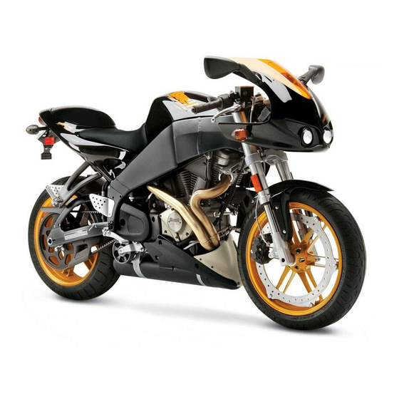
2004 Buell Firebolt: Chassis
2.1
U.S.
LITERS
3.7 gallons
14.0
0.7 gallons
2.6
2.5 quarts
2.4
14 ounces
0.41
1.0 quart
0.95
SOLO
GVWR
RIDING
36 PSI
(248 kPa)
Same as
Solo
38 PSI
(262 kPa)
IN.
MM
0.0177
0.45
0.0248
0.63
0.0177
0.45
0.0154
0.39
WARNING
2-1
Advertisement
Table of Contents


Need help?
Do you have a question about the Firebolt XB12R 2004 and is the answer not in the manual?
Questions and answers