Advertisement
Quick Links
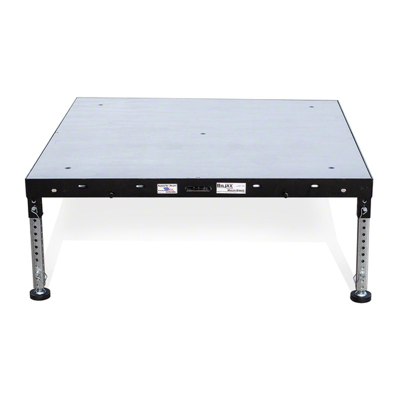
Multi-Stage - Steel Staging
Assembly Instructions
ST8100
All Drawings Are For Illustration Only.
REVISION
E.C.O. 'S
REV
REV
BY
DATE
This drawing is the property of
BilJax INC
., Archbold, Ohio. This equipment was designed with
the understanding that the prints are loaned and will not be reproduced, copied, or used to assist in
making further drawing, apparatus or parts therof, and is to be returned unless otherwise specified.
1972.30
WEIGHT
lbs.
FINISH
MATERIAL SPECIFICATION
UNLESS OTHERWISE SPECIFIED
THE FOLLOWING APPLY:
*DIMENSIONS ARE IN INCHES.
*TOLERANCES ARE AS FOLLOWS
FRACTION
DECIMALS
ANGLES
+/- 1/32"
XX +/- .01
+/- 1/2
XXX +/- .005
1:26
SCALE
*ALL WELDS ARE TO BE CONTINUOUS
3/16" FILLETS.
*ALL WELD FILLETS ARE TO
COMPLETELY FOLLOW THE JOINT
CREATED BY THE MATING SURFACES
OF PARTS JOINED.
COVER
DR
ELB
10-14-19
ST8100 ASSY INST DWGS
BY
DATE
DWG NO.
ARCHBOLD, OHIO 43502
COPYRIGHT
2017
C
P/N : LL-204-50
Last Revision: October 2019
SIZE
B
Advertisement

Related Manuals for BilJax ST8100


Summary of Contents for BilJax ST8100
- Page 1 FRACTION DECIMALS ANGLES +/- 1/32" XX +/- .01 +/- 1/2 XXX +/- .005 10-14-19 1:26 ST8100 ASSY INST DWGS SCALE DATE DWG NO. DATE *ALL WELDS ARE TO BE CONTINUOUS 3/16" FILLETS. SIZE This drawing is the property of BilJax INC ., Archbold, Ohio.
-
Page 2: Step 1 - Site Preparation
DETAIL AE STEP 1 - SITE PREPARATION Determine the exact location where the stage will be erected. For outdoor stages, mudsills are required to distribute the weight (125PSF to 150PSF) on the stage legs. This will prevent the legs from sinking and ease the leveling of the stage. All base pads and mudsills should be placed only on a horizontal surface. MAX. HEIGHT LOAD RATING 6ft-2in 150 PSF 6ft-2in to 16ft-0in 125 PSF STEP 2 - LEG ASSEMBLY The leg sockets on the stage deck fit 1-1/2” sq. stage legs. Use any of the following: 1-1/2” sq. leg with adjustable base pad. Insert base pad into leg and attach with 2-3/8” snap pin in third hole of leg. 1-1/2” sq. leg with adjustable base pad with collar. Insert base pad into leg and attach with 2-3/8” snap pin in second hole of leg. Adjustable legs – Insert adjustable base pad into 1-3/4” sq. leg and attach with 2-3/8” snap pin in third hole of leg. NOTE: Collar of base pad must be in leg for stability. Place a 1-1/2” sq. leg inside the 1-3/4” sq. leg and adjust to desired length. Pin together leg tubes with 2-3/8” snap pin. NOTE: There must be a minimum of a 6”... - Page 3 *ALL WELDS 3/16" FILLET 3/16" FILLET This drawing is the property of This drawing is the property of FRACTION BilJax INC BilJax INC DECIMALS ., Archbold, Ohio. This equipment was designed with ., Archbold, Ohio. This equipment was designed with ANGLES...
- Page 4 STEP 4 - SETTING THE STAGE Place the first stage deck (with legs in all four corner sockets) in back corner of stage site. Align the stage deck so that the studs are toward the inside of the staging site and the slots are toward the outside of the staging site. NOTE: When using 4’ x 4’ decks exclusively, any corner may be used as a starting point. The sides with studs must always face toward the stage site. Slots (facing downward) Studs (sticking outward) Stage Site STEP 5 - SETTING THE STAGE (continued) Set the back row of stage decks first. Insert two legs into each additional stage deck (per Step 3) and attach to previous stage deck by positioning and lowering the slots onto the studs. NOTE: The sides with studs must always STAGE face toward the stage site.
- Page 5 DATE *ALL WELDS ARE TO BE CONTINUOUS 3/16" FILLETS. This drawing is the property of BilJax INC ., Archbold, Ohio. This equipment was designed with *ALL WELD FILLETS ARE TO ARCHBOLD, OHIO 43502 the understanding that the prints are loaned and will not be reproduced, copied, or used to assist in...
- Page 6 *ALL WELDS A SCALE DATE 3/16" FILLETS This drawing is the property of BilJax INC ., Archbold, Ohio. This equipment was designed with *ALL WELD FI This drawing is the property of BilJax INC ., Archbold, Ohio. This equipment was designed with...
- Page 7 3/16" FILLETS. *ALL WELD FILLETS ARE TO *ALL WELD FILLETS ARE TO This drawing is the property of BilJax INC ., Archbold, Ohio. This equipment was designed with This drawing is the property of BilJax INC ., Archbold, Ohio. This equipment was designed with...
- Page 8 3/16" FILLETS. 3/16" FILLETS. SIZE SIZE This drawing is the property of BilJax INC ., Archbold, Ohio. This equipment was designed with *ALL WELD FILLETS ARE TO *ALL WELD FILLETS ARE TO This drawing is the property of BilJax INC ., Archbold, Ohio.
- Page 9 *DIMENSIONS ARE IN INCHES. OF PARTS JOINED. STEP 10J SIZE OF PARTS JOINED. This drawing is the property of BilJax INC., Archbold, Ohio. This equipment was designed with *ALL WELD FILLETS ARE TO *TOLERANCES ARE AS FOLLOWS 1/4 SCALE ARCHBOLD, OHIO 43502...
- Page 10 STEP 10 - INSTALLING FREE STANDING RAMP A ramp should be installed at a 1” of rise to 12” of run. The height of a run is limited to 30” maximum before a landing is required. Determine the size and location of ramp. Example: a 24” tall stage will require a 24’ long ramp. Start at top of ramp. Determine amount of decks required. If a 4’ x 4’ deck is required, begin with it. Example: 24” tall stage = 4’ deck + 8’ deck + 8’ deck + 4’ starter ramp. Pull and hold pin in the unlocked position. Fully insert a ramp leg adapter in the leg socket so that it touches the bottom of the stage deck. Release pin to lock leg in place. Tighten the leg socket wing bolt at each corner socket (underside of stage) where a leg is installed. Attach 1-3/4” sq. leg to ramp adapter with 2-3/8” snap pin. Leg length (without base pad) is approximately 6” shorter than desired height of ramp at leg position. STEP 1B STEP 1D Side Two Side Two Side One Side One STEP 1B STEP 1B STEP 1F WEIG...
- Page 11 *ALL WELDS ARE TO BE CONTINUOUS 3/16" FILLETS. SIZE This drawing is the property of BilJax INC., Archbold, Ohio. This equipment was designed with *ALL WELD FILLETS ARE TO ARCHBOLD, OHIO 43502 the understanding that the prints are loaned and will not be reproduced, copied, or used to assist in...
- Page 12 *ALL WELDS ARE TO BE CONTINUOUS 3/16" FILLETS. SIZE This drawing is the property of BilJax INC., Archbold, Ohio. This equipment was designed with *ALL WELD FILLETS ARE TO ARCHBOLD, OHIO 43502 the understanding that the prints are loaned and will not be reproduced, copied, or used to assist in...
- Page 13 3/16" FILLETS. *ALL WELD FIL This drawing is the property of BilJax INC., Archbold, Ohio. This equipment was designed with *ALL WELD FILLETS ARE TO This drawing is the property of BilJax INC., Archbold, Ohio. This equipment was designed with...
- Page 14 SCALE DATE This drawing is the property of BilJax INC., Archbold, Ohio. This equipment was designed with the understanding that the prints are loaned and will not be reproduced, copied, or used to assist in making further drawing, apparatus or parts therof, and is to be returned unless otherwise specified.
- Page 15 SIZE 3/16" FILLETS. SIZE This drawing is the property of BilJax INC., Archbold, Ohio. This equipment was designed with *ALL WELD FILLETS ARE TO *ALL WELD FILLETS ARE TO This drawing is the property of BilJax INC., Archbold, Ohio. This equipment was designed with...
- Page 16 ST8100 Multi-Stage - Steel Staging Assembly Instructions 125 Taylor Parkway Archbold, OH 43502 Phone: 419.445.8915 Toll Free: 800.537.0540 Fax: 419.445.0367 biljax.com P/N : LL-204-50 Last Revision: October 2019 ©2019 BilJax, Inc.
Need help?
Do you have a question about the ST8100 and is the answer not in the manual?
Questions and answers