Table of Contents
Advertisement
Quick Links
Advertisement
Table of Contents

Subscribe to Our Youtube Channel
Summary of Contents for Triadis VEGA
- Page 1 Pilot’s Manual Document name: VEGA-P-EN Document version: 1.11 Release date: 25/08/2008 triadis engineering GmbH – Eichholzstrasse 7 – Postfach – CH-3254 Messen Phone: +41 (0)31 768 15 15 – Fax: +41 (0)31 768 15 16 – Internet: www.triadis.ch – E-Mail: admin@triadis.ch...
- Page 2 Notes • Vega Pilot’s Manual VEGA-P-EN...
- Page 3 Notes • Vega Pilot’s Manual VEGA-P-EN...
- Page 4 • This equipment does not remove the need to maintain an effective lookout. • Continue to observe the airspace and do not rely on Vega (or FLARM) to announce all objects in the airspace! • If possible, Vega is to be installed as ‘portable equipment’ with an autonomous power supply.
- Page 5 Restrictions on operation • Vega may not be operated in aircraft that are registered or insured in the USA or Canada, or by pilots of the USA and Canada. Likewise businesses are forbidden to operate Vega, if persons on-board the aircraft reside in the USA or Canada or are citizens of the USA or Canada.
-
Page 6: Table Of Contents
Speed warnings ....... . . System and health advisories ......Instrument panel interface • Vega Pilot’s Manual VEGA-P-EN... - Page 7 Frequently Asked Questions ......Feature summary Technical specifications Generated speech Limited Warranty • Vega Pilot’s Manual VEGA-P-EN...
-
Page 8: Introduction
1 INTRODUCTION 1 Introduction Vega is a precision air data sensor and audio processing system designed for use in gliders as an integrated soaring instrument and aid to situational awareness. Vega is small, easy to use, with a simple user interface and can be built into small instrument panels. -
Page 9: Pilot Familiarisation
Be aware of how the instrument is configured in the particular aircraft, and what external devices are connected, as these affect which functions of Vega are available. A blank page at the end of this document is provided for owners to record notes on their individual installation. - Page 10 SD card, however Vega is not an IGC approved logger. A systems view of the Vega is shown in the following figure. It shows the major logical subsystems inside the instrument and the interfaces to external systems in the glider.
-
Page 11: Configuration
SD card, and take the card from one aircraft to another so that their preferences are applied to whichever Vega aircraft they fly. Refer to the Vega Advanced Configuration and Data Link Specification for configuration options and factory default settings. -
Page 12: Air Data System
2 AIR DATA SYSTEM 2 Air data system Vega contains a sophisticated air data sensor and can interface with an external navigation sys- tem to supply a detailed view of the aircraft performance, atmospheric conditions and air mass movement, and certain obstructions in the airspace. -
Page 13: Efis Computer
If a FLARM or external GPS is connected to Vega on NMEA IN, then FLARM aircraft obstruction data and GPS data are also sent to the EFIS. In this sense, Vega operates as a pass-through device (NMEA chain). -
Page 14: Instrument Inputs
FLARM. This allows convenient transfer of flight logs and configurations between the aircraft and the pilot’s PC or EFIS. Furthermore, it enables many pilots in a club or syndicate to use Vega and FLARM with their own customisations. -
Page 15: Sd-Card Requirements
The card may not be used write protected, that is, with the slide switch on LOCK. The card is formatted FAT and can be read and written with a PC card reader or a PDA. Use Vega only with the provided SD card. This SD card matches with industrial standards and has therefore a higher temperature resistance and a higher writing cycles capacity. -
Page 16: Audio And Speech System
3 AUDIO AND SPEECH SYSTEM 3 Audio and speech system The audio system of Vega consists of a multichannel audio mixer, speech generator, and audio generator for variometer sounds. The mixer blends the various inputs in an intelligent fashion in order to provide a clear, pleasant and safe flying experience. - Page 17 Too fast Optimal Circling High pitch Low pitch The tone generator is highly configurable to the pilot’s preferences. The configurations may be changed on the ground or switched between several preprogrammed schemes in flight. This is • Vega Pilot’s Manual VEGA-P-EN...
-
Page 18: Audio During Thermal Encounter
Secondly, it allows the tones to be switched to another scheme in special circumstances, such as when the need arises to search for very weak lift. See the Vega Advanced Configuration and Data Link Specification for details on audio customisation, and some suggested audio schemes emulating other popular variometers. -
Page 19: Speech Messages
The various audio tones may be demonstrated and tested using the Vario Demo dialog in XCSoar. 3.3 Speech messages Vega produces speech messages for FLARM-equipped aircraft traffic and obstruction references; airframe warnings and advisories, and other flight and system status related advisories. These speech messages are played through a loudspeaker or headset. -
Page 20: Message Acknowledgement
3.4 Audio mixer Vega is able to mix other audio signals (radio loudspeaker and headset) and send them to a loud- speaker or headset along with the generated speech messages and audio vario sounds. All audio signals are monitored so that the output at the speaker or headset switches is based on priority. -
Page 21: Audio Fail-Safe
8.3. In the development of Vega, fail-safe behavior was made a high priority. Vega can recognize errors and and it switches into a bypass mode of operation (ERROR LED shines continuously). In bypass mode, the input and output of the audio channels are directly connected. -
Page 22: Traffic And Obstruction Messages
4 TRAFFIC AND OBSTRUCTION MESSAGES 4 Traffic and obstruction messages Vega integrates with FLARM to receive GPS and aircraft obstruction data. The data announced by FLARM are converted to acoustic caution or warning messages. Depending upon the operating mode, traffic references and collision warnings are filtered in accordance with the FLARM Alarm Level. -
Page 23: Flarm Alarm Levels
3.3. Class FLARM event Message Traffic references Reference FLARM collision warnings alarm level 1 FLARM voltage supply Vega battery low warning Caution FLARM collision warnings alarm level 2 FLARM functionality restricted FLARM malfunction Airframe warning Vega battery depleted warning Warning FLARM collision warnings alarm level 3 4.4 FLARM filtering modes... -
Page 24: Filtering In Circling And Cruise
Increasing the mode number always means a reduction of the advance warning time! 4.5 Filtering in circling and cruise Vega has two modes, one for the cruising flight and one for the circling. Vega changes automatically between circling mode and cruise mode. If one changes the alert mode whilst circling, then this change applies to the circling flight mode, similarly when changing the alert mode in the cruise... -
Page 25: Airframe And Advisory Messages
“Landing gear” 5.2 Stall monitor If the stall pressure sensor is installed, Vega is able to provide warnings of imminent stall. The stall monitor is based on principle of detecting a critical angle of attack, and as such requires no compensation for ballast and functions even when the aircraft is accelerating. -
Page 26: Speed Warnings
Depending on the installation, Vega may or may not be aware of flap and airbrake settings and the accuracy of the stall monitor may be affected as a result. For example, if the critical angle of attack was set when the aircraft had airbrakes retracted, but the airbrake switch is not installed, then the aircraft with airbrakes extended may stall without the warning being raised. -
Page 27: System And Health Advisories
Refer to the aircraft’s pilot’s manual and cockpit placards for the relevant limits. Parameters affecting the calculation of these warnings are defined in the Vega Advanced Configu- ration and Data Link Specification. In normal use, they may be set from the EFIS. -
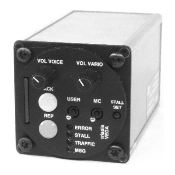
Page 28: Instrument Panel Interface
Lit when there are messages in the message queue. Upon starting up the device, the ERROR LED should be lit. All LEDs are lit while Vega performs memory and system checks (about 10 seconds). After the memory and system check, if an error has been detected the ERROR LED stays lit while the other LEDs remain off. -
Page 29: Volume Knobs
If installed, the external speed command switch, marked ‘SC’ can be used to switch the flight mode used by the EFIS and Vega between cruise or climb. The specific role of this switch is configurable as either a direct switch, or as an override. See Vega Advanced Configuration and Data Link Specification for more details. -
Page 30: Acknowledge Key
6.4.1 Alert mode selection The pilot can select the mode by holding down the Acknowledge key until the Blip tone is heard (after approximately a half second). After releasing the key Vega reads out all 5 modes in sequence: “Mode one, mode two...”... -
Page 31: Operation
7 OPERATION 7 Operation This section describes how the pilot operates Vega, in particular, concentrating on start-up and use in flight. Periodic maintenance of the Vega is required for ongoing use and the required procedures are described in the Vega Installation Manual. -
Page 32: Variometer Volume Check
Interrupt the voltage supply of Vega (e.g. pull the circuit breaker). The ERROR LED will no longer flash and the volume should be just as loud as when Vega was switched on. Test this with the loudspeaker and the headset if installed. -
Page 33: Airframe Switch Test
Set as appropriate for the aircraft aerodynamic condition. Refer to the EFIS documentation for how to perform this operation. In XCSoar, this is performed by selecting the basic settings dialog from menu: CONFIG Setup Basic • Vega Pilot’s Manual VEGA-P-EN... -
Page 34: Efis Data Link
During flight, the EFIS system may be used to change the MacCready, bugs and ballast settings. If a compatible system is used, these settings will automatically be sent to Vega. MacCready values in the EFIS system may be adjusted by the MacCready rocker switch on the Vega panel face; or by the EFIS software. -
Page 35: Support
Important errors are reported as speech messages. • Internal hardware diagnostics may be obtained by sending a special NMEA command to the instrument via the serial port. See Vega Advanced Configuration and Data Link Specifi- cation for details. • Error logs are written to a file on the SD-Card. -
Page 36: Frequently Asked Questions
If the aircraft battery is charged and all wiring has been checked, but the device still does not start up properly, it is most likely that there is insufficient voltage at the power supply to Vega. This may be caused by power wires that are too thin, or that there is too much voltage drop across a circuit breaker. - Page 37 Initial calibration and setting warning limits for stall etc. should also be performed. We recommend that the FLARM ID is set on the ICAO ID of the aircraft. When Vega is put into aircraft other than a glider, then we recommend urgently that the FLARM configuration is specified.
- Page 38 8 SUPPORT • Vega Pilot’s Manual VEGA-P-EN...
-
Page 39: A Feature Summary
Automatic muting of audio when receiving radio communications, or during spoken mes- sages • Volume increases with increasing airspeed to compensate for cabin noise Altimeter • Multistage digital filter • Adjustment by QNH offset Airspeed indicator • Multistage digital filter • Density altitude compensation • Vega Pilot’s Manual VEGA-P-EN... - Page 40 Detects flying too slowly near terrain • Detects landing approach with undercarriage extended • Detects instrumentation failure Configuration • All settings controllable by EFIS/SD card • Glide polar adaptable to any glider type and weight, and with different wingtip options. • Vega Pilot’s Manual VEGA-P-EN...
- Page 41 1x Serial RS-232 connection to GPS, FLARM or third party device (e.g. logger) • GPS and FLARM data pass-through to EFIS • Full integration with open-source XCSoar software • 5V power supply for PDA or GPS • Vega Pilot’s Manual VEGA-P-EN...
-
Page 42: B Technical Specifications
Filter time constant: 1.0 seconds Output rate: 5 Hz Stall monitor Filter time constant: 1.0 seconds Output rate: 5 Hz Accelerometer Accuracy: 2%, offset error 0.04g Range: 2.0 g ( 6.0g) Output rate: 5 Hz • Vega Pilot’s Manual VEGA-P-EN... - Page 43 50 mA typical (when not powering external PDA, volume minimum) Vega has over-voltage protection which disconnects the device from the power source if the input voltage exceeds 16V. Input voltage over 30V will blow the internal fuse. Vega is reverse voltage protected up to -30V.
- Page 44 B TECHNICAL SPECIFICATIONS Environmental Temperature range: -30 to +65 degrees C Humidity: 10-90% non-condensing Shock resistance: not specified Vibration resistance: not specified • Vega Pilot’s Manual VEGA-P-EN...
-
Page 45: C Generated Speech
Status messages Ready for operation Vega is ready for use. Error X-Y Error X-Y is reported. Refer to the Vega Advanced Configuration and Data Protocol Manual for a descrip- tion of the error codes. Mode X FLARM reporting filter level is in the specified Mode. -
Page 46: D Limited Warranty
A the failure of the product is to be attributed to accident, abuse, misuse, carelessness, im- proper modification or repair...
Need help?
Do you have a question about the VEGA and is the answer not in the manual?
Questions and answers